Wireless power transfer via electrodynamic coupling

a wireless power transfer and electrodynamic coupling technology, applied in the direction of dynamo-electric machines, electrical apparatus, influence generators, etc., can solve the problems of unstoppable wireless world, unstoppable wireless world, and ever-growing hunger for portable power, so as to reduce the exposure of human body and reduce the operating frequency

Active Publication Date: 2017-06-01
UNIV OF FLORIDA RES FOUNDATION INC
View PDF17 Cites 5 Cited by
  • Summary
  • Abstract
  • Description
  • Claims
  • Application Information

AI Technical Summary

Benefits of technology

[0031]Unlike inductively coupled WPT systems, where strong electric and magnetic fields permeate the transmitting media, the strong magnetic field in the electrodynamically coupled system (from the magnet) is limited to the receiving region (near the magnet). This will greatly reduce the exposure of human body to strong magnetic fields.

Problems solved by technology

These maintenance procedures typically require physical contact or wire connections with the devices, which may be inconvenient, difficult, or costly in applications such as harsh-environment sensor networks or implanted medical devices.
Even where batteries can be easily recharged, the ever-growing hunger for portable power has presented an un-ignorable technical challenge.
With the proliferation of wireless devices, the power cable acts as a virtual umbilical cord and presents a cumbersome hindrance to a completely unfettered wireless world.
However, because of the typically low power densities of the ambient energy sources and limited energy conversion efficiencies, current energy-harvesting systems have been targeting very low-power applications (1 μW-1 mW).
Higher output powers are possible by using volumetrically larger energy harvesters, but this becomes size-prohibitive for compact applications.
Another disadvantage of energy harvesting devices is that they are at the mercy of the environment.
Intermittency and variability of the environmental energy source result in overdesign of the energy harvester to ensure adequate power generation and require more complicated power electronics to regulate voltage and power flow, problems that are exacerbated in unpredictable environments.
Additionally, due the absorptive nature of this radiated energy, the transmission path must be clear of objects, which may be difficult to realize in many applications.
While the inductively coupled WPT systems have the benefit of using magnetic fields to pass through many materials and objects (as compared to electric fields), there are practical limits to both power levels and efficiency, especially for powering wireless sensors.
However, there are strict safety limits on magnetic and electric fields for RF power transmission that greatly restrict the range, efficiency, and thus application of these systems.
As explained above, since the power is proportional to the square of the voltage, in order to deliver a certain amount of power, either the frequency or the flux density in the receiving coil (the area of the receiving coil is usually predetermined) needs to be sufficiently high, which may not be achievable without violating the safety limits.
However, the time-varying electromagnetic fields that permeate the power transmission media can cause safety hazards.
For even lower frequencies, the flux density safety limit is higher.
Accordingly, safety limits and coil size put an upper limit on the power level that can be transmitted via inductively coupled WPT.
These high frequencies create additional system limitations.
First, the high-frequency electromagnetic fields may induce large eddy currents in any conductive materials that are present in the power transmission path.
In many home, medical, or industrial applications, power transmission through the metal cases may be required, so eddy current losses will reduce the overall efficiency and may cause unwanted heating problems.
Another issue is robustness.
As a result, the system performance is very sensitive to the resonator parameters, since the transmitter and receiver must be precisely matched.
From the manufacturing aspect, the required tolerances in the coil inductance and capacitance are very tight, which can be costly or even impossible to realize.
Even if initially matched or manually tuned, uncontrollable parasitic capacitances / inductances, for example due to temperature, humidity, and / or coil positions, can lead to mismatches in resonant frequency.
In addition, these uncontrollable parasitic capacitances / inductances can drastically reduce the transmit power and efficiency.
The design of the tuner / controller increases the cost and complexity of the system.
Furthermore, tuning the resonant frequencies of the transmitter and the receiver makes it difficult to power an array of receivers with one single transmitter.
This causes interference or cross talk between receivers.
That is, the current flow in one receiver may induce significant voltage in other receivers.
To mitigate this interference, additional complicated power flow control circuits may be required.
Because of the various limitations on inductive WPT, application of inductive WPT has been limited to short-range, highly specific applications such as electric vehicles and consumer electronic charging pads.
While clever electronic control circuits have overcome some of the tuning challenges, there continue to be challenges in widespread implementation of inductive WPT because of the range, power, and efficiency limits of the existing inductive WPT structures.

Method used


Image

  • Wireless power transfer via electrodynamic coupling
  • Wireless power transfer via electrodynamic coupling
  • Wireless power transfer via electrodynamic coupling

Examples


Embodiment Construction

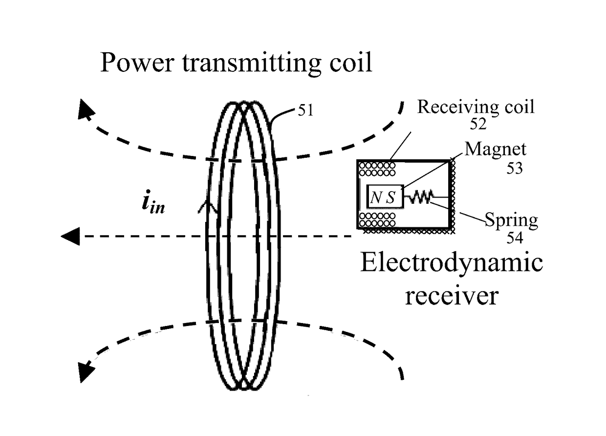
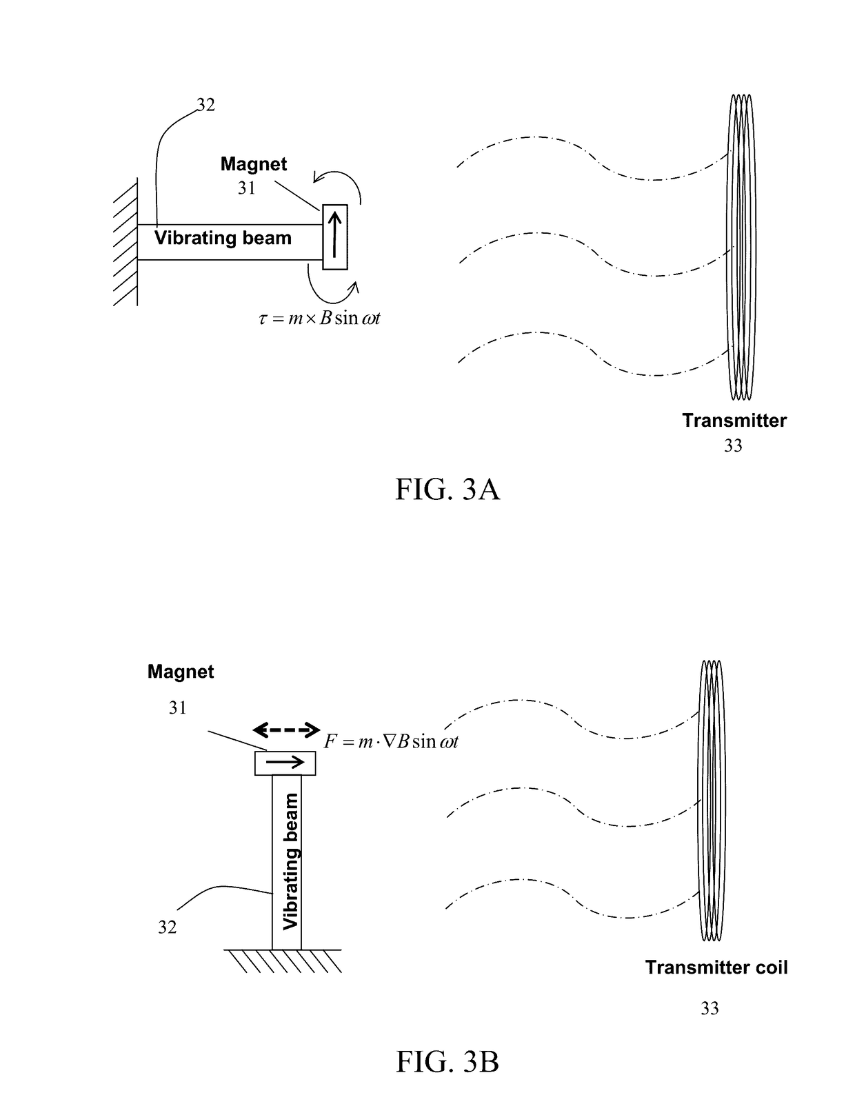
[0052]Embodiments of the invention provide wireless power transmission (WPT) systems that actively deliver power from a source to a receiver, providing deterministic control over the power transfer. Embodiments of the invention provide wireless power transfer devices and methods utilizing an electrodynamically coupled approach to WPT. In accordance with certain embodiments of the invention, an electrodynamically coupled WPT system is provided in which a current-carrying coil (transmitter) generates a low-frequency, time-varying magnetic field that induces a sinusoidal mechanical forcing function on a permanent magnet residing on a receiver. The resulting magnet motion (e.g., vibration) can be converted into electrical power via electromechanical conversion. The electromechanical conversion can be electrodynamic, piezoelectric, electrostatic, or a combination of one or more conversion methods.

[0053]The receiver is similar to a vibrational energy harvester, where, in certain embodimen...


PUM


Abstract

Wireless power transmission (WPT) systems are provided. According to an embodiment, the WPT system uses one or more power transmitting coils and a receiver for electromagnetically coupled wireless power transfer. The electrodynamic receiver can be in the form of an electrodynamic transducer where a magnet is allowed to oscillate near a receiving coil to induce a voltage in the receiving coil, a piezoelectric transducer where the magnet causes a vibrating structure with a piezoelectric layer to move, an electrostatic transducer where movement of the magnet causes a capacitor plate to move, or a combination thereof. An alternating magnetic field from the transmitting coil(s) excites the magnet in the receiver into mechanical resonance. The vibrating magnet then functions similar to an energy harvester to induce voltage / current on an internal coil, piezoelectric material, or variable capacitor. Embodiments utilize magnetic coupling and electromechanical resonance for safe, spatially distributed, low-frequency power delivery to portable devices.

Description

CROSS-REFERENCE TO RELATED APPLICATION[0001]The present application is a continuation application of U.S. application Ser. No. 13 / 989,293, filed May 23, 2013, which is a 371 U.S. national stage application of International Application No. PCT / US2011 / 046748, filed Aug. 5, 2011, which claims the benefit of U.S. Provisional Application Ser. No. 61 / 417,059 filed Nov. 24, 2010, which are hereby incorporated by reference in their entirety, including all figures, tables and drawings.BACKGROUND OF THE INVENTION[0002]Battery-powered systems are becoming increasingly ubiquitous for industrial, personal, and medical use. Because of the finite energy storage available to battery-powered systems, battery replacement and / or charging must be performed periodically over the lifetime of these systems. These maintenance procedures typically require physical contact or wire connections with the devices, which may be inconvenient, difficult, or costly in applications such as harsh-environment sensor ne...

Claims


Application Information

Patent Timeline
Patent Type & Authority Applications(United States)
IPC IPC(8): H02J50/12H02N1/08H02K35/02
CPCH02J50/12H02N1/08H02K35/02H02K99/10H02J50/50H02J50/001H02J50/90H02J50/70Y02T10/70H02J50/10H02J50/00
Inventor ARNOLD, DAVID PATRICKCHENG, SHUOCHALLA, VINOD REDDY
Owner UNIV OF FLORIDA RES FOUNDATION INC
Why Eureka
Try Eureka