Microelectronic thermal valve

a micro-electronic and thermal valve technology, applied in the field of valves, can solve the problems of increased response times and unreliable thrust performance of ar 2 units, and achieve the effects of increasing response times, enhancing thrust to power ratio, and maximizing energy and propulsion efficiency

Active Publication Date: 2017-06-08
PURDUE RES FOUND INC
View PDF17 Cites 13 Cited by
  • Summary
  • Abstract
  • Description
  • Claims
  • Application Information

AI Technical Summary

Benefits of technology

[0008]The evaporation of water that serves as thrust production mechanism also has the benefit of providing cooling to the local structure. In the units with throat aspect ratios of two, cooling coefficients of performance as high as 11 have been measured. Unfortunately the thrust performance of the AR˜2 units has proven to be unreliable due to meniscus instability leading to increased response times and uncommanded impulses. However, this intermittent performance has shown a greatly enhanced thrust to power ratio as much as 5 mN / W, an order of magnitude greater than AR˜4, because more vaporization energy is extracted from the optimal aspect ratio such that energy and propulsion efficiency can be maximized.

Problems solved by technology

Unfortunately the thrust performance of the AR˜2 units has proven to be unreliable due to meniscus instability leading to increased response times and uncommanded impulses.

Method used


Image

  • Microelectronic thermal valve
  • Microelectronic thermal valve
  • Microelectronic thermal valve

Examples


first embodiment

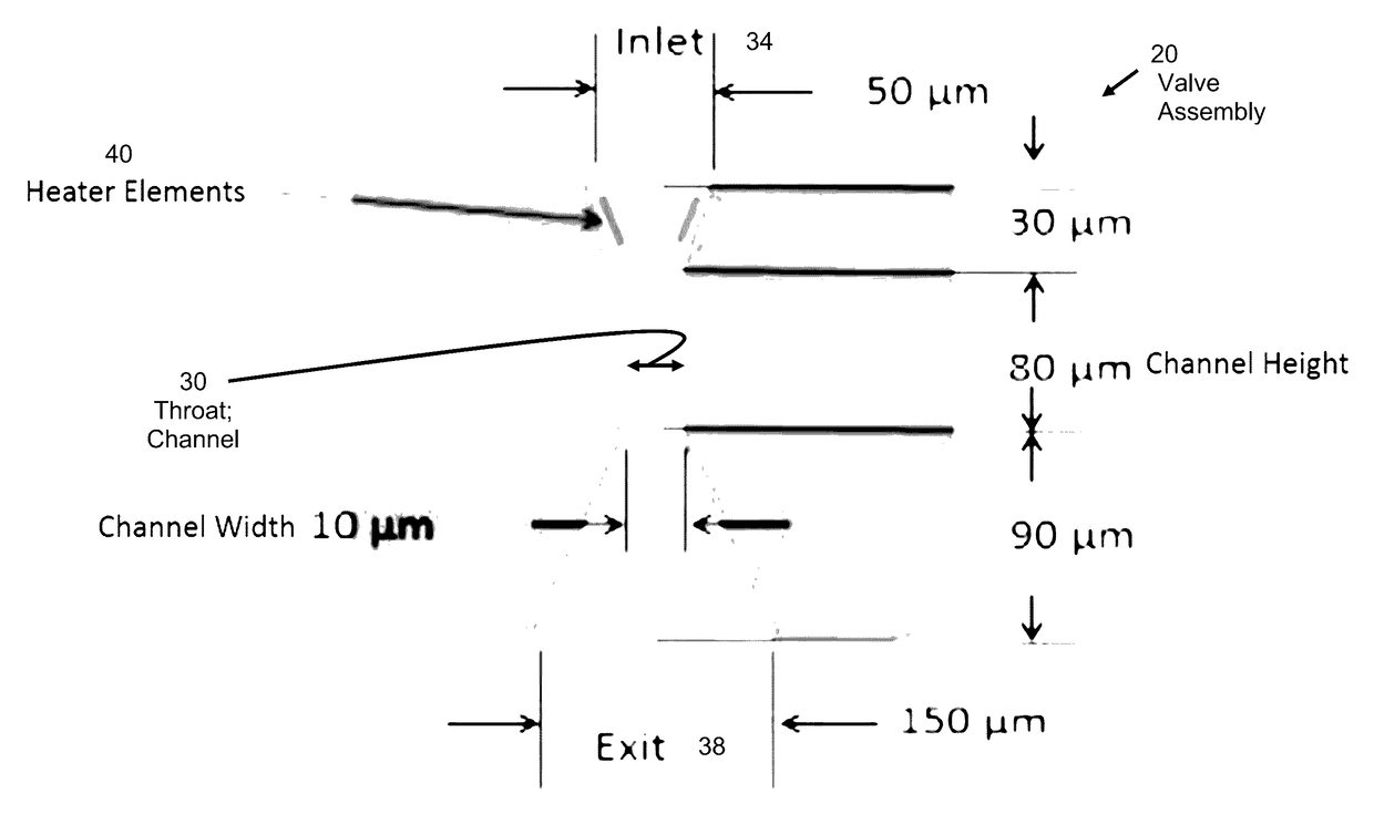
[0109]FEMTA nozzles included throat aspect ratios (width / depth) at the upper and lower ends of the design spectrum which yielded FEMTA with AR˜2 seen in FIGS. 2.4-1A, B, C, and D, and FEMTA with AR˜8 seen in FIGS. 2.4-2A, B, and C. The different aspect ratios were achieved by varying the etch time in step 3 of the fabrication procedure.

[0110]The nichrome heater elements were produced at a 10 micrometer target width which should give ample margin for error if over etching occurred (see FIGS. 2.4-3A and B). This produced heaters with resistances approximately 25% of the target value but was compensated by using a lower voltage drive signal.

[0111]Two 200 micron thick silicon wafers were split by scratching with a diamond scribe so that 4 halves were processed. The heater thickness was doubled to reduce current density so to eliminate electromigration as a factor and the insulating oxide layer thickness was increased by a factor of 4 to reduce thermal diffusion into the substrate. Enhan...

third embodiment

[0113]The small batch yield and somewhat inconsistent dimensions led to yet another fabrication embodiment. The wafer thickness of the third embodiment devices was chosen to be 500 microns due to availability and ease of handling. Four wafers were selected to represent the four aspect ratios defined previously. The internal nozzle design was consistent with both gen-1 and gen-2 designs with the greatest alteration being the width and depth of the exit chamber. Wet etching of the exit was prohibited by the lifetime of the oxide mask in the etching solution so DRI etching was to be used instead. This meant that only the inlet side lithography and oxide etch was performed in steps i, ii, and iii of the process and the wet etch time in step iv was reduced to 18 minutes since only the 24 micron deep inlet need be etched at this time.

[0114]The heater material was changed from nichrome to vanadium with sputtering time in step v increased to 3 hours with all other settings the same. The van...

second embodiment

[0146]The second embodiment FEMTA nozzles were tested in the 4.2 cubic meter vacuum chamber using the microNewton thrust stand. A test vessel was fashioned from a 1½×1½×1 inch block of Teflon® with power connections and a fixed pressure relief valve.

[0147]The relief valve from Gen2 testing was used to reduce pressure from atmospheric to just above vapor pressure so that water would not be expelled during the pump down process. Teflon was chosen to replace the aluminum model used in thermalvac testing to reduce galvanic corrosion due to metals having a dissimilar galvanic indices in an aqueous environment.

[0148]The use of platinum heaters improved the corrosion problems experienced with chrome and vanadium so that a more comprehensive thrust testing format could be implemented. These heaters also operated at a lower voltage so that applied power could be controlled by a labview program with current augmentation from a unity gain power amplifier.

[0149]The thrust history of a 65 mW tes...


PUM


Abstract

A microfabricated valve with no moving parts. In one embodiment, the valve includes a reservoir of a liquid that is in fluid communication with an outlet channel having a throat that is less than 100 microns wide. Preferably, the channel is an elongated slit. The configuration of channel is adapted and configured such that surface tension of the liquid prevents flow out of the channel. A heater increases the temperature of the meniscus of the fluid, until a portion of the fluid is ejected from the channel. The ejection of the fluid creates both a thrusting effect and a cooling effect.

Description

CROSS REFERENCE TO RELATED APPLICATION[0001]This application claims the benefit of priority to U.S. Provisional Patent Application Ser. No. 62 / 263,719, filed Dec. 6, 2015, incorporated herein by reference.GOVERNMENT SUPPORT CLAUSE[0002]This invention was made with government support under NNX13AR02A awarded by the National Aeronautics and Space Administration. The government has certain rights in the invention.TECHNICAL FIELD[0003]The present application relates to valves including thermally activated valves, and including valves that operate a thrusting device.BACKGROUND[0004]This section introduces aspects that may help facilitate a better understanding of the disclosure. Accordingly, these statements are to be read in this light and are not to be understood as admissions about what is or is not prior art.[0005]In many applications, there is a need for a minute amount of fluid to pass through a valve. At micro-scales, ensuring the desired release volume is difficult to impractical...

Claims


Application Information

Patent Timeline
Patent Type & Authority Applications(United States)
IPC IPC(8): F16K99/00B64G1/40
CPCF16K99/0017F16K99/0036F16K2099/0092F16K2099/0094B64G1/401B64G1/10B64G1/50F16K99/0021F16K99/0044F16K2099/0074F16K2099/008F16K2099/0096
Inventor ALEXEENKO, ALINACOFER, ANTHONY GEORGEHEISTER, STEPHEN DOUGLAS
Owner PURDUE RES FOUND INC
Why Eureka
Try Eureka