Monitoring systems and methods for electrical machines

a monitoring system and electrical machine technology, applied in the field of systems and methods of detection, characterization, and diagnosis, can solve the problems of increasing the frequency of partial discharge, increasing the number of fatigue cracks, and partial discharges

Active Publication Date: 2017-06-15
GENERAL ELECTRIC CO
View PDF3 Cites 20 Cited by
  • Summary
  • Abstract
  • Description
  • Claims
  • Application Information

AI Technical Summary

Problems solved by technology

Fatigue cracking and partial discharge (PD) events are both issues for electric generator systems.
Partial discharges tend to increase the number of fatigue cracks, and an increase in the number of fatigue cracks tends to increase the frequency of partial discharges.
Cumulative partial discharges may cause fatigue cracking events.
Partial discharges cause progressive deterioration of insulating materials, ultimately leading to an electrical breakdown.
Repetitive PD events cause irreversible mechanical and chemical deterioration of the insulating material.
Damage is caused by the energy dissipated by high energy electrons or ions, ultraviolet light from the discharges, ozone attacking the void walls, and cracking as the chemical breakdown processes liberate gases at high pressure.
A history of internal PD in a high-voltage system eventually triggers electrical treeing.
A significant problem with electrical detection of partial discharges is that the detection equipment is highly susceptible to electromagnetic noise, which can lead to false detection of partial discharges, typically as false positives.
In high voltage systems, however, the spike caused by a partial discharge may be very small compared to the amplitude of the system voltage and may be missed, leading to a false negative.
Usually the equipment subjected to testing also needs to be taken off-line, energized from a high-voltage source, and then tested, which requires a lot of time and equipment.
Conventional PD measurement systems cannot detect fatigue cracks and may detect but do not locate the PD events.
Fatigue cracking events generate acoustic emissions.

Method used


Image

  • Monitoring systems and methods for electrical machines
  • Monitoring systems and methods for electrical machines
  • Monitoring systems and methods for electrical machines

Examples


example 1

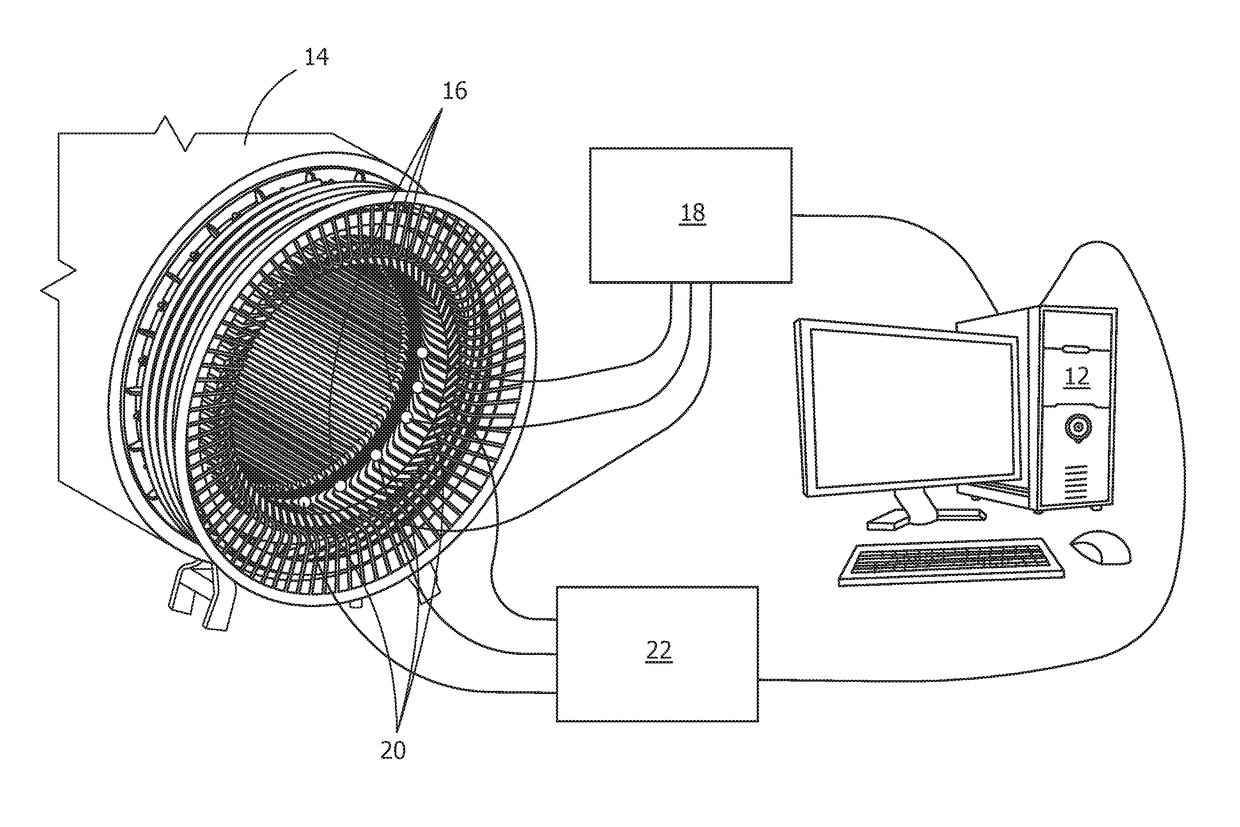
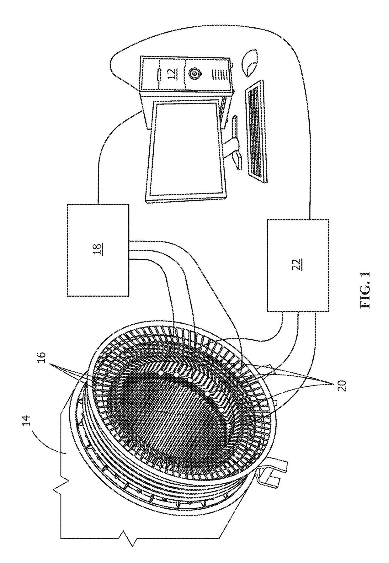
[0044]An AE monitoring system and a PD monitoring system were tested in combination on a metal bar serving as a model electric generator system. The monitoring system included transducers, an amplifier, and an oscilloscope. A Tesla coil was used to produce arcing to a predetermined location on the metal bar to simulate a PD event. ASTM E976 (“Standard Guide for Determining the Reproducibility of Acoustic Emission Sensor Response”) was followed to break a pencil lead against the predetermined location on the metal bar to simulate a fatigue cracking event. The 2H, 0.5-mm diameter pencil lead extended about 3 mm through a guide ring prior to the lead break. Sensors were located on both sides of the predetermined location on the metal bar and collected AE monitoring system data and PD monitoring system data.

[0045]The AE monitoring system was able to detect signals from both the AE event and the PD event, whereas the PD monitoring system was only able to detect signals from the PD event....

example 2

[0046]Sample data from a PD monitoring system and an AE monitoring system, synchronized and monitoring the same sample, show how data fusion allows an AE monitoring system to benefit from a PD monitoring system, and vice versa. A plot of electrical signals 80 measured by the partial discharge sensors is shown in FIG. 6 as a function of AC phase 82. An artificial plot of expected acoustic emissions signals from the same sample as measured by the AE sensors and synchronized with the electrical signals is shown in FIG. 7. The crack event data 84 from the AE sensors is corroborated by the absence of any associated signals from the PD sensors, and the PD event data from the PD sensors is corroborated and enhanced by the associated AE signals 86 from the AE sensors.


PUM

PropertyMeasurementUnit
AC) frequencyaaaaaaaaaa
frequencyaaaaaaaaaa
frequencyaaaaaaaaaa

Abstract

A monitoring system includes an acoustic emission monitoring system including acoustic emission sensors, a partial discharge monitoring system including partial discharge sensors and synchronized with the acoustic emission monitoring system, and a computer receiving acoustic emission data from the acoustic emission sensors and electrical data from the partial discharge sensors. The computer is configured to classify a first statistical event as a fatigue cracking event by pattern recognition of the acoustic emission data and determine a first location and a first damage condition resulting from the fatigue cracking event, classify a second statistical event as a partial discharge event by pattern recognition of the acoustic emission data or the electrical data, and fuse the acoustic emission data and the electrical data for the second statistical event and determine a second location and a second damage condition resulting from the partial discharge event. Methods of monitoring are also disclosed.

Description

FIELD OF THE INVENTION[0001]The present invention is directed to systems and methods of detection, characterization, and diagnosis. More specifically, the present invention is directed to systems and methods for the detection and characterization of fatigue cracking and partial discharge events in electrical machines.BACKGROUND OF THE INVENTION[0002]Fatigue cracking and partial discharge (PD) events are both issues for electric generator systems. The phenomena are related in that each may be a contributing factor of the other. Partial discharges tend to increase the number of fatigue cracks, and an increase in the number of fatigue cracks tends to increase the frequency of partial discharges. A partial discharge is a localized dielectric breakdown of an electrical insulation system that does not bridge the space between two conductors. A partial discharge generates high frequency transient current pulses that persist for a time period in the range of nanoseconds up to a microsecond....

Claims


Application Information

Patent Timeline
Patent Type & Authority Applications(United States)
IPC IPC(8): G01N29/14G06N5/04G06N99/00G01N29/44G01R31/34G06N20/00
CPCG01N29/14G01N29/4445G01R31/343G01N2291/0289G06N5/047G01N2291/2638G06N99/005G01R31/1209G06N20/00G01N27/92G01N29/2418G01N29/4481G01N2291/0258G01R31/1272G01R31/1227
Inventor DEHGHAN NIRI, EHSANROSE, CURTIS WAYNEWITNEY, ANDREW BATTON
Owner GENERAL ELECTRIC CO
Why Eureka
Try Eureka