Sorbent comprising carbon and nitrogen and methods of using the same

Active Publication Date: 2017-06-22
MIDWEST ENERGY EMISSIONS CORP
View PDF1 Cites 21 Cited by
  • Summary
  • Abstract
  • Description
  • Claims
  • Application Information

AI Technical Summary

Benefits of technology

[0012]In some embodiments, the sorbent of the present invention can be regenerated and reused, reducing disposal of spent sorbents and decreasing the cost of mercury removal.
[0013]In some embodiments, preparation or promotion of the sorbent of the present invention can occur on site. In some embodiments, onsite preparation and promotion (e.g., in the furnace, in the mercury-containing gas, in the injection/transport system, or a combination thereof) of the sorbent provides certain advantages. For example, the treatment system can be combined with the carbon (or sorbent) injection system at the end-use site. With this technique, the halogen/halide precursor and/or promoter is introduced to the carbon-air (or other gas, such as a combustion or gasification gas) mixture in a transport line (or other part of the sorbent storage and injection system) or mercury-containing gas, or prepared in-flight in the mercury-containing gas. In some embodiments, the nitrogen layer structure surface layer can be prepared in-flight (e.g., in transport line, in the mercury-containing gas, or combinations thereof) with the introduction of a nitrogen precursor and/or promoter. In some embodiments, this can provide benefits over current conventional concepts for treating sorbents off-site such as: capital equipment costs at a treatment facility are eliminated; costs to operate the treatment facility are eliminated; there are no costs for transporting carbon and additive to a treatment facility; the inventive process uses existing hardware and operation procedures; the inventive technology ensures that the sorbent is always fresh, and thus, more reactive; no new handling concerns are introduced; there are no costs for removing carbon from treatment system; the inventive process allows rapid on-site tailoring of additive-sorbent ratios in order to match the requirements of flue gas changes, such as may be needed when changing fuels or reducing loads, thus further optimizing the economics; the inventive technology reduces the amount

Problems solved by technology

Mercury (Hg) emissions have become a health and environmental concern because of their toxicity and ability to bioaccumulate.
The amount of standard sorbents (e.g., activated carbon) needed to serve the market is

Method used


Image

  • Sorbent comprising carbon and nitrogen and methods of using the same
  • Sorbent comprising carbon and nitrogen and methods of using the same
  • Sorbent comprising carbon and nitrogen and methods of using the same

Examples


examples

[0126]Various embodiments of the present invention can be better understood by reference to the following Examples which are offered by way of illustration. The present invention is not limited to the Examples given herein.

Part I. Preparation of Composite Sorbent Comprising Activated Carbon Core and Nitrogen Layer Structure.

example i-1

Impregnation of Nitrogen Precursors into a Char Surface Followed by Carbonization and Activation of the Impregnated Char

example 1a

Carbon Precursor

[0127]A carbon (20×60 mesh) prepared by steam activation of a lignite char was stirred with an aqueous solution of dextrose and ethanolamine in ratio of 1 part of carbon to 0.016 parts of ethanolamine and 0.034 parts of dextrose. The water solvent was removed by rotovaporation and the impregnated carbon was air-dried. The dried material was reactivated at 750° C. for 2 hours under nitrogen stream.


PUM

PropertyMeasurementUnit
Fractionaaaaaaaaaa
Fractionaaaaaaaaaa
Temperatureaaaaaaaaaa

Abstract

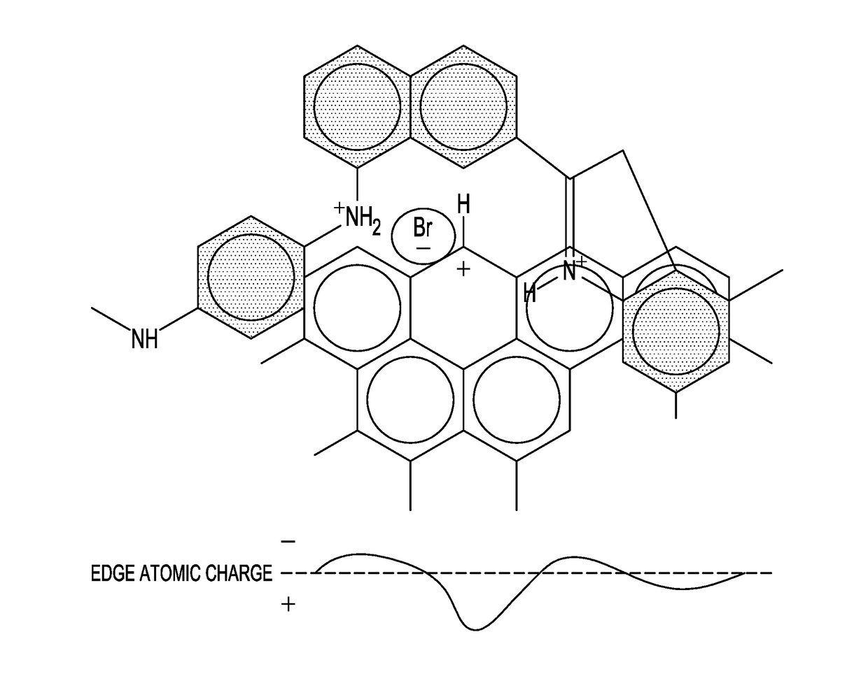
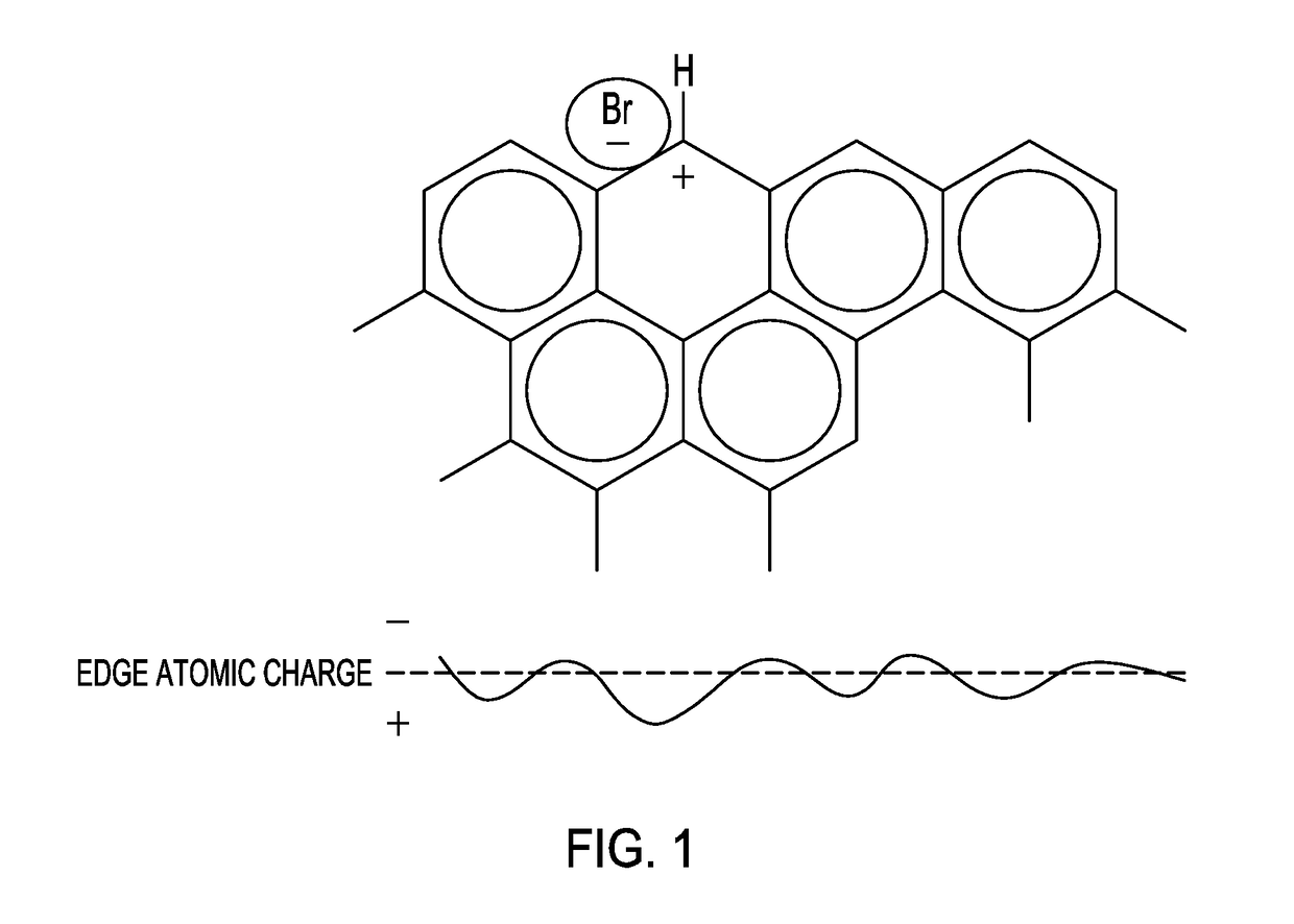
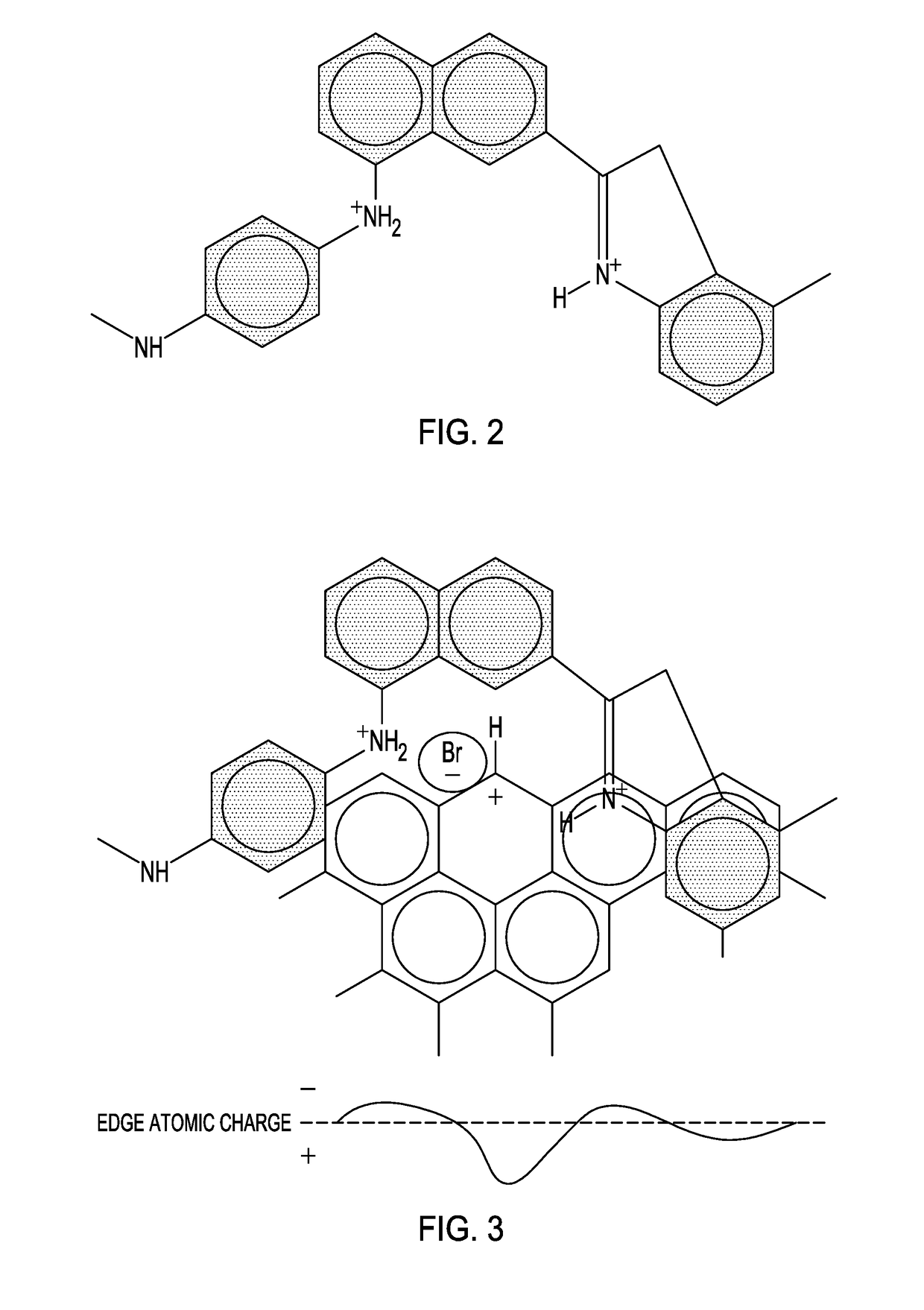
The present invention relates to sorbents including carbon and nitrogen. In various embodiments, the sorbent can remove mercury from a mercury-containing gas that includes sulfur(VI) such as SO3 more efficiently than other sorbents. The sorbent can include a graphene edge comprising an active site for mercury oxidation and a nitrogen layer structure including cationic nitrogen atoms, neutral nitrogen atoms, or a combination thereof proximate the active site.

Description

CROSS-REFERENCE TO RELATED APPLICATIONS[0001]This application is a continuation-in-part of and claims the benefit of priority under 35 U.S.C. §120 to U.S. Utility application Ser. No. 14 / 195,360, filed Mar. 3, 2014, which claims the benefit of priority under 35 U.S.C. §119(e) to U.S. Provisional Patent Application Ser. No. 61 / 773,549, filed Mar. 6, 2013, the disclosures of which are incorporated herein in their entirety by reference.BACKGROUND[0002]Mercury (Hg) emissions have become a health and environmental concern because of their toxicity and ability to bioaccumulate. The U.S. Environmental Protection Agency (EPA) has issued regulations for the control of mercury emissions from waste-to-energy, cement production, and coal-fired power plants. Mercury in flue gas from industrial sources (e.g., power plants) can be captured by sorbents such as activated carbon, which can then be removed by particulate separation devices. The amount of standard sorbents (e.g., activated carbon) need...

Claims


Application Information

Patent Timeline
IPC IPC(8): B01J20/22B01D53/81B01D53/64B01J20/20B01J20/30
CPCB01D2253/25B01J20/22B01J20/205B01J20/20B01D2253/202B01D53/64B01D53/81B01D2257/60B01D2253/102B01J20/3085B01D53/02B01D53/025B01D53/04B01D53/10B01D53/8665B01D2253/304B01D2257/602B01D2258/0283B01J20/28004B01J20/3204B01J20/3208B01J20/3236B01J20/324B01J20/3293C01B32/336C01B32/342C01B32/36
Inventor OLSON, EDWIN S.PAVLISH, JOHN HENRY
Owner MIDWEST ENERGY EMISSIONS CORP
Why Eureka
Try Eureka