
Hand for Nanocoated Fabric

a nano-coating fabric and hand technology, applied in the field of coatings, can solve the problems of halogenated materials forming toxins, wide-spread property damage and injuries, and affecting the health of people,

Active Publication Date: 2017-06-29
TEXAS A&M UNIVERSITY
View PDF4 Cites 4 Cited by
  • Summary
  • Abstract
  • Description
  • Claims
  • Application Information

AI Technical Summary

Benefits of technology

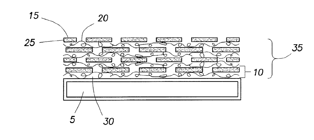
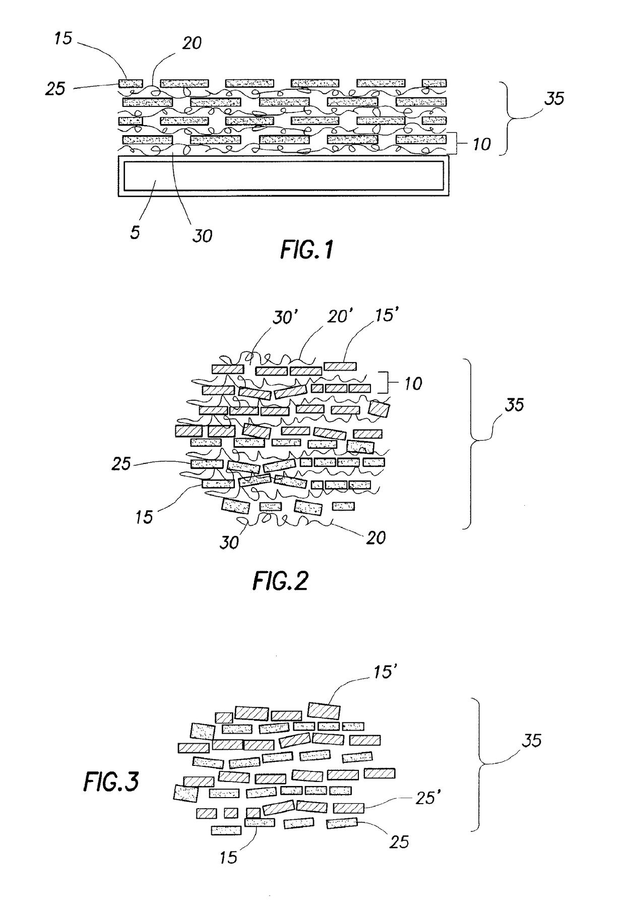
The patent describes a method for coating a substrate to make it flame resistant. The method involves applying a cationic solution to the substrate to create a cationic layer, then exposing this layer to an anionic solution to create an anionic layer. These layers, when combined, create a layer that is resistant to fire. The materials used in the solution can include polymers, colloidal particles, nanoparticles, nitrogen-rich molecules, geopolymers, carbon-based fillers, or any combination of these. The method may also involve agitating the substrate and using different types of cationic and anionic solutions. The technical effect of this invention is the creation of a flame-resistant substrate through the application of two layers that work together to protect the substrate from fire.

Problems solved by technology

Fire-related occurrences have caused widespread property damage and injuries.
Drawbacks to such halogenated materials include the potential for harm to the environment and humans.
For instance, such halogenated materials may form toxins.
Other drawbacks include a lack of durability that may be typical in some instances to the brominated compounds.
However, drawbacks to use of nanoparticles include increased processing viscosity and modulus of the final polymer material, such as foam or fabric.
Further drawbacks include inadequate flame suppression and melt-dripping.
However, conventional layer by layer methods have drawbacks.
Drawbacks include increasing stiffness of the fabric by worsening the hand (i.e., feel) of the fabric.
Such drawbacks may be due to bridges between individual fibers in the fabric and / or depositing aggregates during the layering process.

Method used


Image

  • Hand for Nanocoated Fabric
  • Hand for Nanocoated Fabric
  • Hand for Nanocoated Fabric

Examples


example 1

[0061]Preparation of Deposition Mixtures.

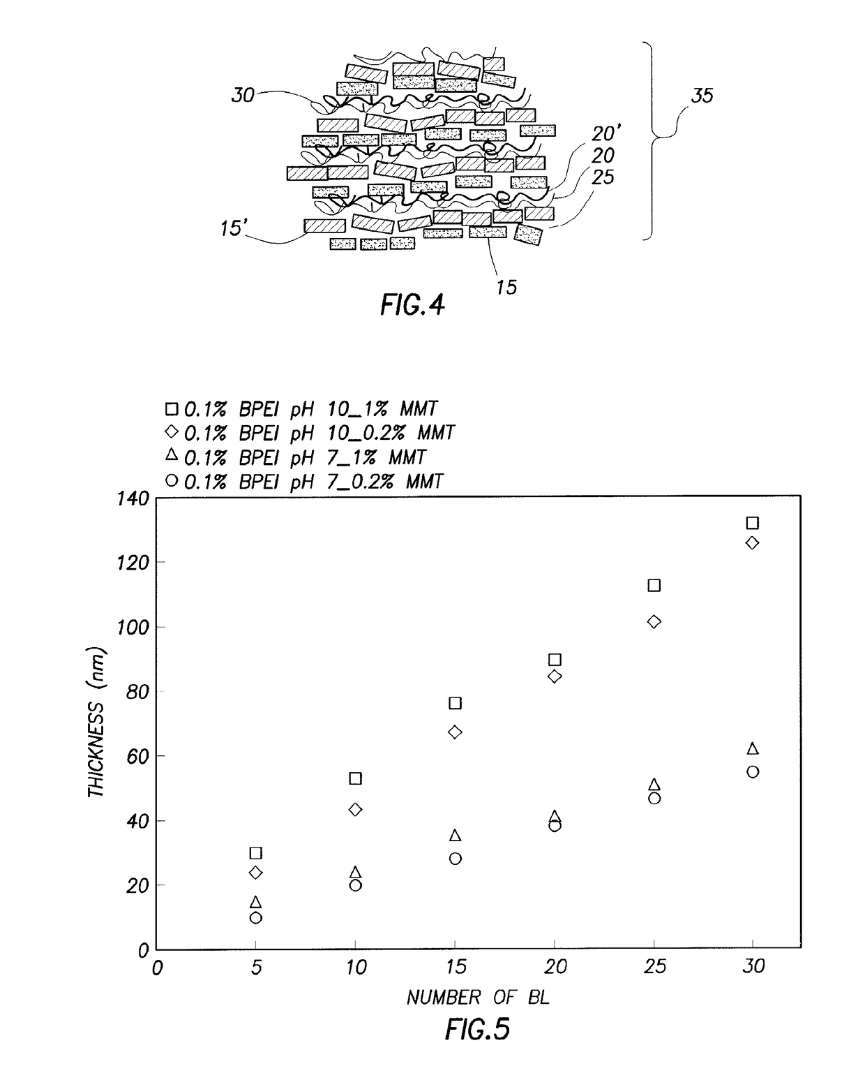
[0062]Cationic deposition solutions were prepared by dissolving 0.1 wt. % branched polyethylenimine, with a molecular weight of 25,000 g / mol (commercially available from Aldrich of Milwaukee, Wis., into 18.2 MΩ deionized water from a Direct-QTM 5 Ultrapure Water System (commercially available from Millipore of Billerica, Mass.). The unadjusted pH of this solution was 10.3, but this value was adjusted to 7 and 10 by adding IM hydrochloric acid (36.5-38.0% HCl available from Mallinckrodt Chemicals of Phillipsburg, N.J.). Sodium montmorillonite (MMT) (Cloisite® Na+ a trademark of Southern Clay Products, Inc. of Gonzales, Tex.) was exfoliated by adding it to deionized water (0.2 or 1.0 wt. %) and slowly rolling for 24 h, to produce the anionic deposition mixtures. MMT had a cationic exchange capacity of 0.926 meq / g and a negative surface charge in deionized water. Individual platelets had a density of 2.86 g / cm3, with a planar dimension of 10-1,0...

example 2

[0091]Southern Clay Products. Inc. (Gonzales, Tex.) supplied the natural sodium montmorillonite (MMT) (Cloisite® Na+ a trademark of Southern Clay Products, Inc.) used in this study. MMT had a cationic exchange capacity of 0.926 meq / g and a negative surface charge in deionized water. Individual platelets had a density of 2.86 g / cm3, diameter of 10-1000 nm (most have d>200 nm) and a thickness of 1 nm. Cationic polyacrylamide (Superfloc® C-491, a trademark of American Cyanamid Company) was provided by CYTEC (West Paterson, N.J.). This was a copolymer containing 5 mol % of positively-charged repeat units. Cationic poly (diallyldimethylammonium chloride) (PDDA) and branched polyethylenimine (BPEI) (Mw=25,000 g / mol and Mn=10,000 g / mol) were purchased from Aldrich (St. Louis, Mo.). Polystyrene (PS) film, with a thickness of 250 μm, was purchased from Goodfellow (UK) and used as the substrate for transmission electron microscopy. Single side polished (100), 500 μm thick silicon wafers (Univ...

example 3

[0098]Open-cell PU foams from NIST were coated with 10 and 40 bilayers of BPEI (at pH 8 and 10) and MMT. The onset of degradation and percent char at 500° C. determined by TGA for different foam coatings, was shown in FIGS. 11a), b). At 400° C. the highest char percentage was achieved with the pH 8 BPEI coating (11.73 wt. % char from foam coated with 40 bilayers). The coating made with BPEI pH 8 had higher clay concentration and was more dense, which may protect the foam from further degradation. Based on the success of the TGA measurements (FIGS. 11a), b)), larger foam pieces with different coatings, as well as a bare one, were placed in an oven and heated up from room temperature to 400° C. and then held for 30 minutes to observe the degradation of foams. The uncoated foam melted and stuck to the ceramic crucible and could not be detached with tweezers. The char from the foams coated with BPEI (pH 8 or pH 10), and MMT was easily removed from the crucibles. Foam coated with pH 8 BP...


PUM

PropertyMeasurementUnit
Timeaaaaaaaaaa
Frequencyaaaaaaaaaa
Frequencyaaaaaaaaaa

Abstract

A method includes coating a substrate to provide a flame resistant substrate. In an embodiment, the method includes exposing the substrate to a cationic solution to produce a cationic layer deposited on the substrate. The cationic solution comprises cationic materials. The cationic materials comprise a polymer, a colloidal particle, a nanoparticle, a nitrogen-rich molecule, a geopolymer, a carbon-based filler, or any combinations thereof. The method also includes agitating the substrate. The method further includes exposing the cationic layer to an anionic solution to produce an anionic layer deposited on the cationic layer to produce a layer comprising the anionic layer and the cationic layer. The anionic solution comprises a layerable material.

Description

BACKGROUND OF THE INVENTION[0001]Field of the Invention[0002]This invention relates to the field of coatings and more specifically to the field of flame retardant coatings for substrates of foam or fabric.[0003]Background of the Invention[0004]Fire-related occurrences have caused widespread property damage and injuries. It is well known that a wide range of commonly used materials are flammable. To reduce the hazards from such flammable materials, flame retardants have been developed. Such flame retardants include halogenated materials. Halogenated materials typically include brominated compounds and phosphinated compounds. Drawbacks to such halogenated materials include the potential for harm to the environment and humans. For instance, such halogenated materials may form toxins. Other drawbacks include a lack of durability that may be typical in some instances to the brominated compounds.[0005]The use of nanoparticles has been developed to overcome such drawbacks. However, drawbac...

Claims


Application Information

Patent Timeline
IPC IPC(8): C09D5/18D06M11/79D06M11/72C08J9/36D06M15/285D06M15/61D06M10/02
CPCC09D5/185C08J2375/06D06M11/79D06M10/02C08J9/365D06M15/285D06M11/72D06M2200/30C08J2375/04C08J2479/02C08J2205/05C08J2201/038D06M2101/06C08J2205/06C08J2405/08D06M15/61B32B5/02D06M15/03D06M15/3562B05D1/36D06M13/44
Inventor GRUNLAN, JAIME C.GUIN, TYLER C.
Owner TEXAS A&M UNIVERSITY
Learn More