
Biointerface layer for analyte sensors

Pending Publication Date: 2017-07-06
DEXCOM
View PDF7 Cites 14 Cited by
  • Summary
  • Abstract
  • Description
  • Claims
  • Application Information

AI Technical Summary

Benefits of technology

The invention introduces a layer that prevents the accumulation of cells, proteins, and other living organisms on the outermost layers of a sensor. This layer helps to increase the lifespan of the sensor and reduce inaccuracy in vivo. By reducing inflammation and other biological responses, the accumulation of biological species on the sensor is minimized, resulting in more accurate readings.

Problems solved by technology

A challenge associated with long-term use of continuous sensors and other medical devices is biomaterial-associated inflammation, which is the inflammation caused by implantation of foreign materials into the body.
The formation of a barrier cell layer around the implanted device can result in impaired tissue integration.
In the case of a continuous sensor, biomaterial-associated inflammation can impair analyte transport from tissues to the sensor surface, whether by creating a diffusion barrier or active consumption of analytes.
The FBGC response to implantable materials results in fibrous capsule formation that impedes sensor function through the modulation of glucose diffusion through dense fibrotic “scar-tissue” layers.
These interferents can cause sensor inaccuracy due to the constant change in transport properties at the sensor / tissue interface.
Aside from diffusion limitations, there exists an active cellular component of the biomaterial-associated inflammatory cascade, involving inflammatory and wound healing cells; these cells that can be activated by implanted materials can actively consume glucose and produce H2O2, which can also lead to sensor inaccuracy.

Method used


Image

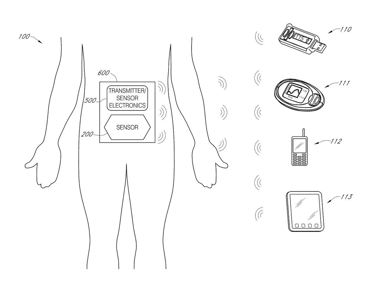
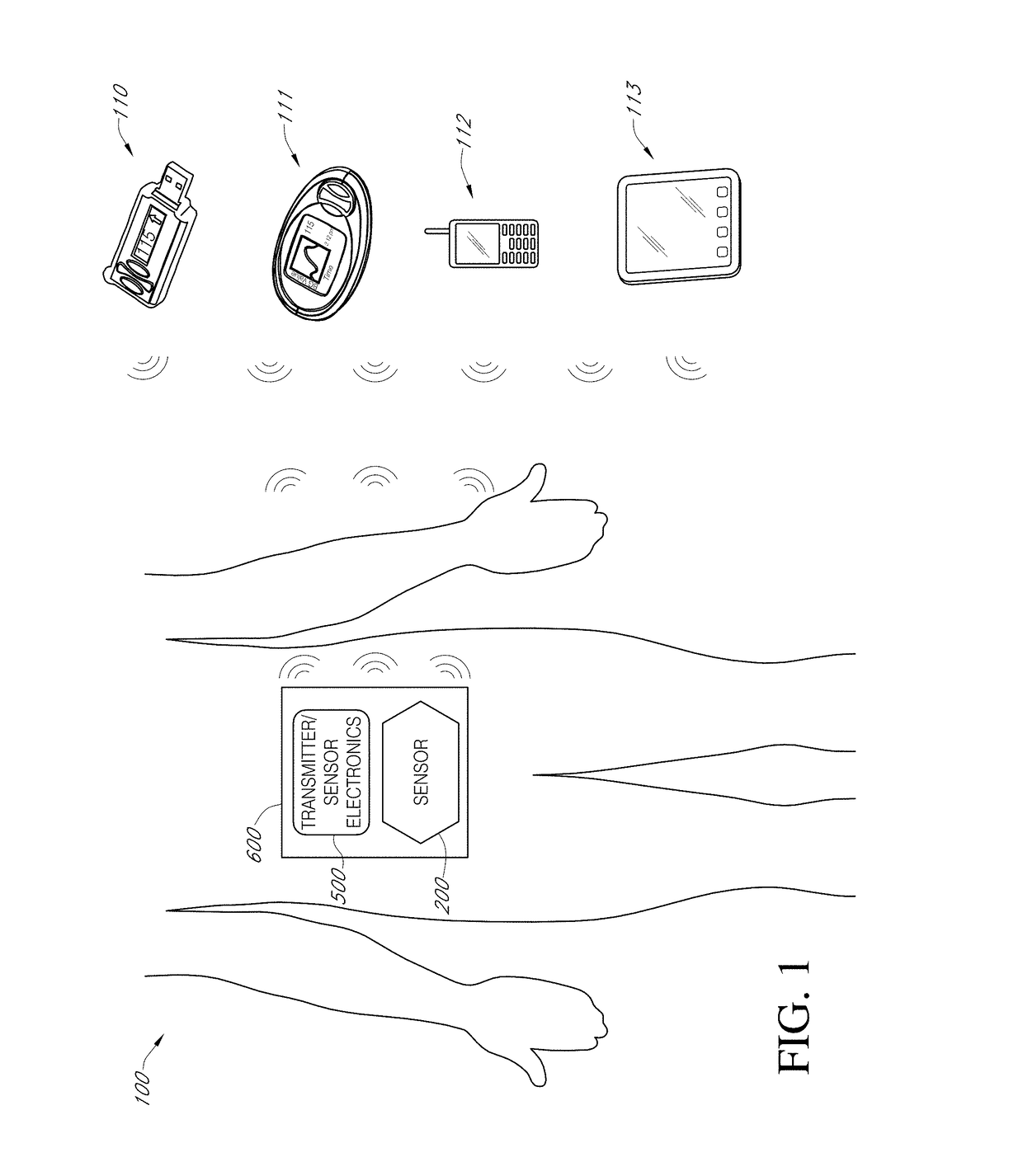
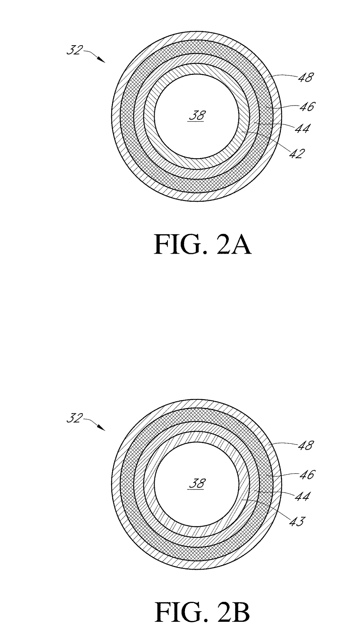
  • Biointerface layer for analyte sensors
  • Biointerface layer for analyte sensors
  • Biointerface layer for analyte sensors

Examples


example 1

Biointerface Polymers and Characterization

[0317]Various biointerface polymers were prepared using different amounts of hard segments, PEG, and sulfobetaines. The hard segments (HS) were polyurethanes or polyureas prepared from diisocyanates reacted with diol or diamine chain extenders of less than 12 carbon units. The particular formulations are shown in Table 1.

TABLE 1PEGBetaineHSMnPDIName(wt. %)(wt. %)(wt. %)(Da)(Mw / Mn)SBL-3201835107,0001.7SBL-10354025127,0001.6SBL-12103561,0001.6SBL-927343177,4001.7SBL-8232735140,0002.1RL-7*004245,0001.7*Comparative.

example 2

Characterization Analysis

[0318]Sensors were built as described in the section entitled “sensor systems.” The in vitro response time was tested and compared to a sensor without the biointerface layer. It was found that the sensor with the biointerface layer had the same T95 response time as the sensor without the biointerface layer, indicating that the biointerface layer did not slow the response times of a glucose sensor (FIG. 5)

[0319]The in vivo response time was also tested in pig over the course of 15 days. In particular continuous sensors with SBL-3 and crosslinked SBL-9 biointerface layers were compared to a sensor without a biointerface layers. It was likewise found that there was no difference in response times for the sensors with and without the biointerface layer (FIG. 6). This again showed that the biointerface domain did not affect the glucose sensor response time.

[0320]The cal-check performance of sensors without a biointerface layer and sensors dip coated with 5 wt. % ...

example 3

Antifouling Properties

[0333]The mechanisms of protein adsorption and antifouling properties of the biointerface layer were explored. The use of zwitterions embedded within and physically, rather than covalently, contained in a polymer are believed to work via the migration of these hydrophilic species to the interface between the polymer and the environment. Biointerface layer made from SBL-10 was tested by X-ray photoelectron spectroscopy (XPS) in a dry state and after soaking. It was found that the atomic concentration of Sulfur on the SBL-10 coated surface of sensor tip did not increase before soaking (dry state, 0.3%) and after soaking (0.2%), which indicate there was no migration to the surface of the zwitterionic segments in the polymer chain (FIG. 13). Thus, while not wishing to be bound by theory, it is believed that the biointerface layer creates a loosely bonded water layer at the surface which prevents the adsorption of proteins and cells (FIG. 12).

[0334]As another theory...


PUM

PropertyMeasurementUnit
Atomic weightaaaaaaaaaa
Contact angleaaaaaaaaaa

Abstract

Disclosed are devices for determining an analyte concentration (e.g., glucose). The devices comprise a sensor configured to generate a signal associated with a concentration of an analyte and a sensing membrane located over the sensor. The sensing membrane comprises a biointerface layer which interfaces with a biological fluid containing the analyte to be measured. The biointerface layer comprises a biointerface polymer, wherein the biointerface polymer comprises polyurethane and / or polyurea segments and one or more zwitterionic repeating units. The biointerface layer increases sensor longevity and decrease sensor inaccuracy by inhibiting accumulation of cells, proteins, and other biological species on the outermost layers of the sensor.

Description

INCORPORATION BY REFERENCE TO RELATED APPLICATIONS[0001]Any and all priority claims identified in the Application Data Sheet, or any correction thereto, are hereby incorporated by reference under 37 CFR 1.57. This application claims the benefit of U.S. Provisional Application No. 62 / 273,155, filed Dec. 30, 2015; U.S. Provisional Application No. 62 / 273,142, filed Dec. 30, 2015; and U.S. Provisional Application No. 62 / 273,219, filed Dec. 30, 2015. Each of the aforementioned applications is incorporated by reference herein in its entirety, and each is hereby expressly made a part of this specification.FIELD[0002]The subject matter disclosed herein relates to devices for measuring a biological analyte in a host and to components of such devices.BACKGROUND[0003]Electrochemical sensors are useful for determining the presence or concentration of a biological analyte, such as blood glucose. Such sensors are effective, for example, at monitoring glucose in diabetic patients and lactate durin...

Claims


Application Information

Patent Timeline
IPC IPC(8): A61B5/1486A61K36/185A61K31/46A61K38/28A61K31/045A61B5/00A61K31/465A61K31/56A61K31/137A61K31/515A61B5/145A61K33/00A61K31/485
CPCA61B5/14865A61K33/00A61K36/185A61K31/46A61K38/28A61K31/045A61B5/0004A61K31/465A61K31/56A61K31/137A61K31/515A61B5/14532A61B5/14546A61K31/485A61B5/002G01N27/3275A61B2562/12C08G18/4833C08G18/755C08G18/0828C08G18/12C08G18/3857C08G18/4018C08G18/44C12Q1/002C12Q1/006A61B5/1486A61B5/1473C12N11/089C12N11/093C08G18/3234C12N11/08G01N27/40C08L39/06C08L69/00C08L75/04G01N27/3273G01N33/66
Inventor LEE, TED TANGDENNIS, ANDREW TRININWANG, SHANGERZOU, JIONG
Owner DEXCOM
Learn More