Eureka AIR delivers breakthrough ideas for toughest innovation challenges, trusted by R&D personnel around the world.

Implantable valve and method

a technology of venous valves and valves, applied in the field of venous valves, can solve the problems of cvi untreated risks, major injury and death, and cvi thrombosis risks, and achieve the effect of inhibiting fibrosis formation and reducing the risk of thrombosis

Active Publication Date: 2017-07-13
VENARUM MEDICAL LLC
View PDF5 Cites 74 Cited by
  • Summary
  • Abstract
  • Description
  • Claims
  • Application Information

AI Technical Summary

Benefits of technology

The invention is a device that helps to prevent blood clots from forming in the veins of patients with certain heart conditions. It includes a leaflet valve that is built into a polymer frame. The leaflets are flexible and made of a material that is smooth and durable. When the valve is opened and closed, it allows blood to flow smoothly through it, reducing the risk of clot formation. This device can be used in diseased vessels and is designed to mimic the natural functions of the heart as closely as possible.

Problems solved by technology

Venous valve reflux causes stagnant blood to pool in the leg leading to fluid / blood cell leakage into the skin and other tissues.
The risks related to untreated CVI are severe and include major injury and death from deep vein thrombosis (DVT); DVT is the formation of a blood clot in deep veins typically in the legs, thighs, or pelvis.
In mild cases, CVI may cause chronic itchy skin, slight pain and swelling; in moderate to severe cases, CVI may cause lifestyle interfering edema, ulcerations and infections (cellulitis, lymphangitis).
Surgical correction of refluxing valves is complicated and expensive.
Long-term outcomes are unpredictable and procedural risks are high.
Although these new catheter-based techniques provide simplified treatment, their best outcomes are limited to recanalization of the vein, not minimizing venous reflux or reversing the long-term symptoms of CVI and acute DVT.
Early attempts at developing a prosthetic venous valve often led to tilting of the valve, thrombus formation at the valve, continued reflux from leaflet thickening or other problems after the valve was delivered.

Method used


Image

  • Implantable valve and method
  • Implantable valve and method
  • Implantable valve and method

Examples


example

[0074]An early prototype implantable valve representative of FIG. 5 was manufactured as follows:

[0075]Tooling Fabrication[0076]a. A dip-coating valve mold was designed in CAD and 3D printed in ABS plastic and machined as the intended negative shape of the final expanded inside diameter of the heat-set frame, with machined and rounded features within the body intended for the valve structure. The valve mold was dipped in solvent to condition and level the surface. The valve mold was then coated in a thin layer of silicone to create a smooth, non-traumatic surface for the intended polymer material over-mold;[0077]b. A heat-setting mandrel was fabricated from stainless steel 10 mm rod as the intended negative shape of the final expanded valve and heat-set frame, with 8 mm ends and a 10 mm bulge in diameter and rounded features within the body for the intended valve structure and frame;

[0078]Frame Fabrication[0079]a. A circumferential patterned frame was designed for an integrated valve...


PUM


Abstract

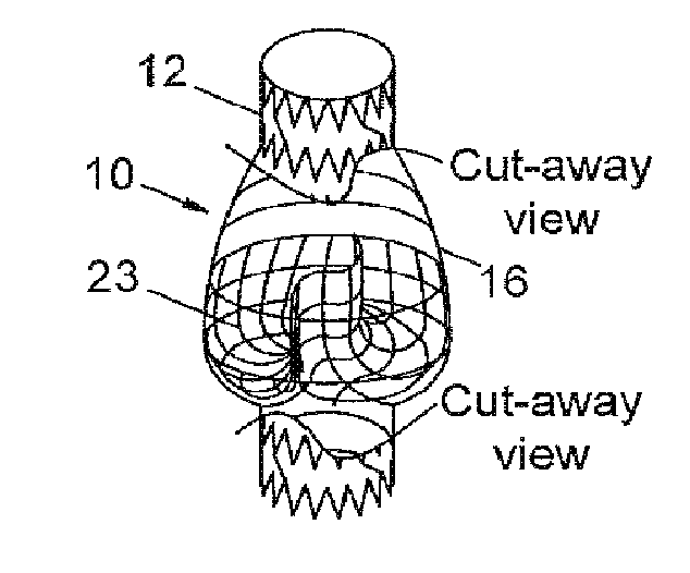
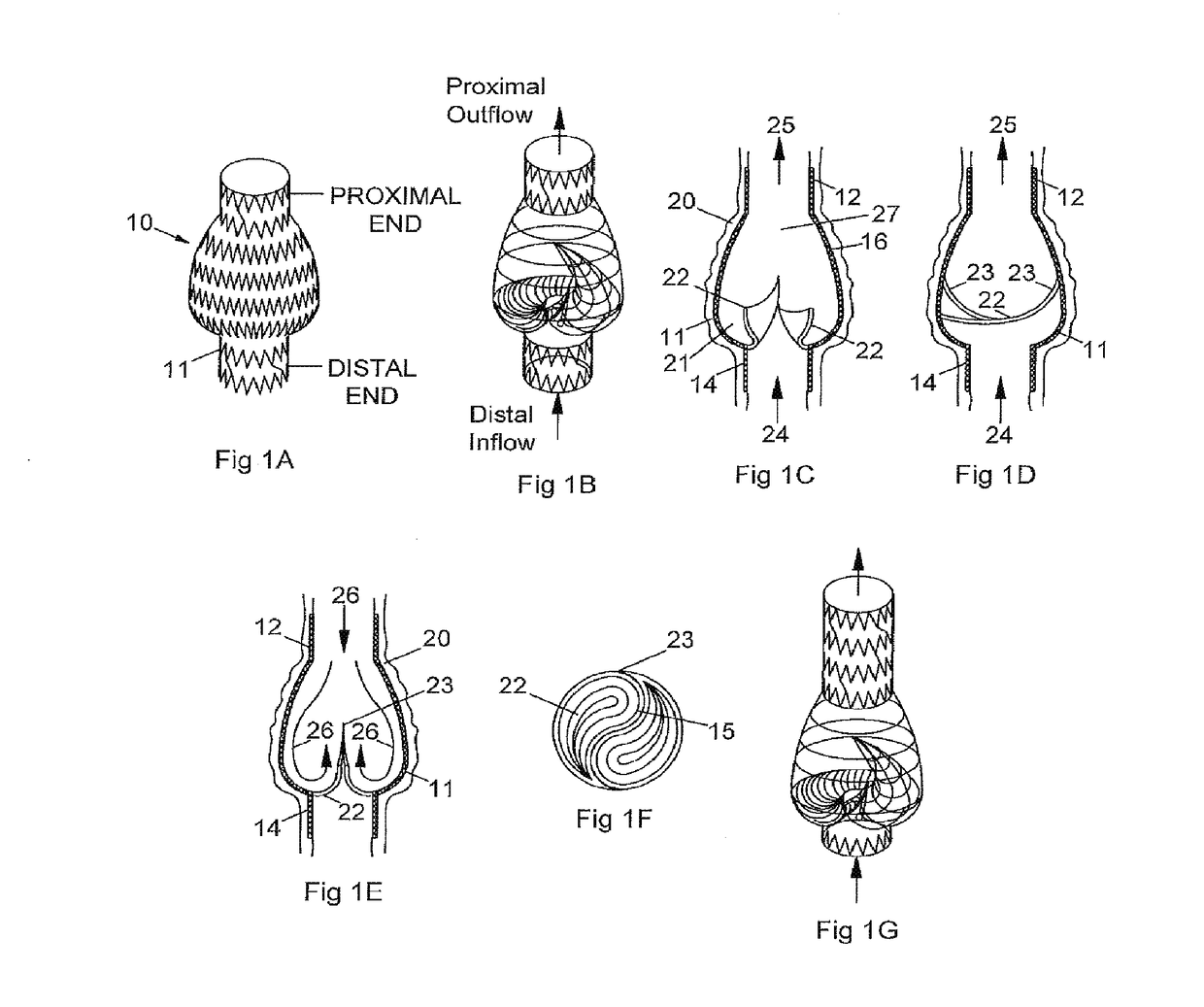
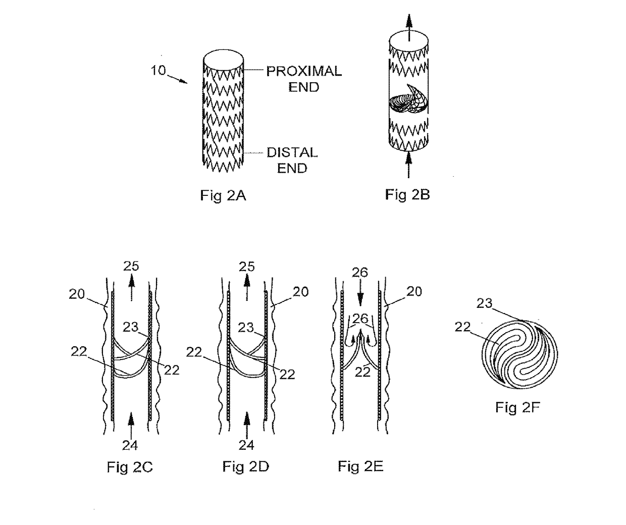
Implantable valve for treating venous insufficiency having a self-expanding frame encased in polymer having a distal section for blood in-flow, a bulbous center section and a proximal section for blood out-flow. Polymeric leaflets have proximal ends forming a valve outlet which opens and closes in response to venous blood flow and distal portions integral with the inner polymer surface of the distal end of said bulbous section. The leaflets define a predominantly biomimetic sinus region with the bulbous section. Opening of the valve induces flushing of blood from the sinus region for smooth non-traumatic blood flow through said valve.

Description

CROSS-REFERENCE TO RELATED APPLICATIONS[0001]The present application claims priority on prior U.S. Provisional Application Ser. No. 62 / 284,923, filed Oct. 13, 2015, which is hereby incorporated herein in its entirety by reference.FIELD OF THE INVENTION[0002]This invention relates to an implantable vascular or non-vascular valve and method, and more particularly, to an implantable venous valve for treating venous insufficiency, related venous valve incompetence and method. The implantable valve enables predominantly unidirectional optimal flow of a liquid, preferably blood; it consists of a frame composed of an expandable scaffold embedded partially or fully in a biocompatible, thrombus-resistant polymer where the frame surrounds, is connected to, and is part of a functioning inner-valve. The implantable valve can be delivered endovascularly from a catheter within a vessel, and are preferably expandable from a compressed configuration to an expanded configuration.BACKGROUND OF THE IN...

Claims


Application Information

Patent Timeline
Patent Type & Authority Applications(United States)
IPC IPC(8): A61F2/24A61F2/915
CPCA61F2/2475A61F2/2418A61F2/915A61F2230/0028A61F2002/91575A61F2230/0093A61F2250/0039A61F2210/0014A61F2230/0069A61F2230/0076A61F2250/0036A61F2240/001A61L27/042A61L27/045A61L27/06A61L27/18
Inventor KIRK, TAYLORFILACHEK, ANDREWBURPEE, JANET
Owner VENARUM MEDICAL LLC
Why Eureka
Eureka Blog
Learn More