Etching device and etching method

Active Publication Date: 2017-07-20
ROBERT BOSCH GMBH
View PDF0 Cites 11 Cited by
  • Summary
  • Abstract
  • Description
  • Claims
  • Application Information

AI Technical Summary

Benefits of technology

The present invention is a method for etching materials using both plasma-assisted and plasma-free techniques. This allows for both isotropic and anisotropic etching. Additionally, the invention includes a design feature that helps achieve a high energy density of the plasma. These technical effects improve the precision and quality of etching processes.

Problems solved by technology

Wet chemical methods are often not usable here, since very closely adjacent functional elements become stuck during the subsequent drying of the MEMS structure.
In this case, however, the etching rate is limited, causing the maximum usable volume of the sacrificial layer to be limited.
A great challenge is to completely remove the sacrificial structures in the isotropic etching step.
However, the etching rate is often limited by the vapor pressure of the used chemical (only approximately 3 torr in the case of XeF2).
This may result in an etching delay or even a complete stop of the etching progress when the sacrificial layer etching is resumed.
In order to avoid this, it is no longer possible to work with plasma-assisted methods, since no ion bombardment is possible on buried structures.
This results in high costs for at least three etching modules and a handling system in order to be able to hold the wafer in a vacuum between the individual process steps.
Moreover, long process durations result from multiple separate etching and handling steps and a distribution of the error possibilities, since all modules have to be available at the same time.
In addition, there are increased maintenance costs because four system elements have to be serviced, a complication due to four different system elements including different software control, if necessary, and an increased risk of product damage due to multiple handling.
There is no way to use the plasma-activated species for isotropic etching at a high etching rate.
Similarly, there is no way to remove buried natural oxide on etch fronts with the aid of gaseous HF.

Method used


Image

  • Etching device and etching method
  • Etching device and etching method
  • Etching device and etching method

Examples


Embodiment Construction

[0038]Identical reference symbols and numerals in the figures denote identical elements or elements having an identical function.

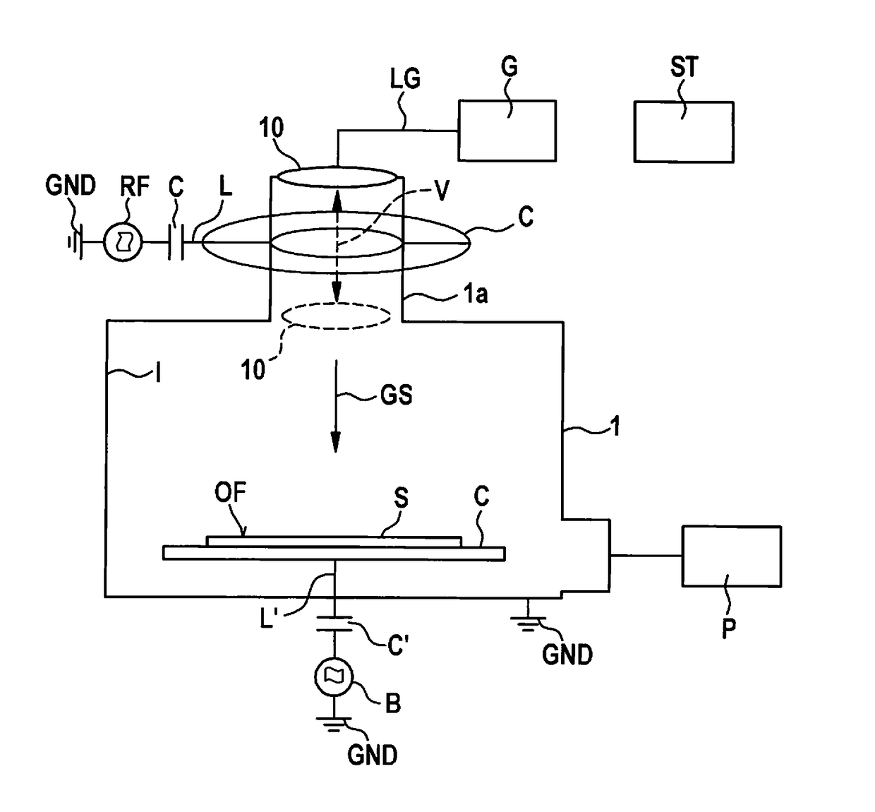
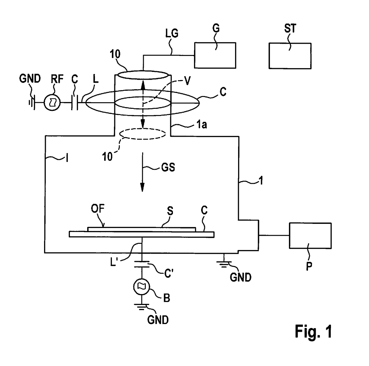
[0039]FIG. 1 shows a schematic cross-sectional representation for elucidating an etching device and a corresponding etching method according to a first specific embodiment of the present invention.

[0040]In FIG. 1, reference numeral 1 denotes an etching chamber, within which a chuck C is situated, on which a substrate S having a surface OF is clamped. The clamping takes place, for example, with the aid of suction nozzles or a mechanical clamping device. A width of etching chamber 1 is advantageously only slightly greater than the diameter of chuck C in order to achieve a suitable etching gas density.

[0041]Connected to etching chamber 1 is a pump device P for producing a desired process pressure and for pumping off the etching gas, in particular when a change of the etching gas is required. With the aid of an electrical line L′, chuck C is connected via a ca...


PUM

PropertyMeasurementUnit
Temperatureaaaaaaaaaa
Areaaaaaaaaaaa
Distanceaaaaaaaaaa

Abstract

An etching device and an etching method. The etching device includes an etching chamber and a chuck located therein for clamping a substrate to be etched, a plasma generating device surrounding the etching chamber in an area and a gas nozzle distribution device for introducing etching gas, which is situated above the chuck in such a way that an etching gas stream is directed essentially perpendicular to a surface of the substrate to be etched. A moving mechanism may be used to change the distance between the gas nozzle distribution device and the chuck as a function of the etching mode.

Description

CROSS REFERENCE[0001]The present application claims the benefit under 35 U.S.C. §119 of German Patent Application No. DE 10 2016200506.5 filed on Jan. 17, 2016, which is expressly incorporated herein by reference in its entirety.FIELD[0002]The present invention relates to an etching device and an etching method.[0003]Although applicable to arbitrary structures, the present invention and the problems underlying it are explained by referring to micromechanical structures in silicon, in which sacrificial layers are removed.BACKGROUND INFORMATION[0004]Micromechanical components based on silicon, for example, sensors or micromirrors, are generally made up of one or multiple conductive functional layers of silicon. The areas of the functional layers that represent the movable part of the MEMS are situated directly on a sacrificial layer. The non-movable areas are, in contrast, connected directly on the substrate without a sacrificial layer. Movable and fixed areas are connected with one a...

Claims


Application Information

Patent Timeline
IPC IPC(8): H01J37/32
CPCH01J37/3244H01J2237/334H01J37/32798B81C1/00531H01J37/32449C23C16/50C23C16/455
Inventor KAELBERER, ARNDZIELKE, CHRISTIANARTMANN, HANSBREITSCHAEDEL, OLIVERSTAFFELD, PETER BORWIN
Owner ROBERT BOSCH GMBH
Why Eureka
Try Eureka