Fill packaging method and fill packaging machine for liquid packing material

a liquid packing material and packaging machine technology, applied in the directions of transportation and packaging, packaging, transit packaging, etc., can solve the problems of insufficient suppression of packing material intrusion poor sealing, and inability to push out granulates by the heat sealing bars, so as to improve productivity, suppress the effect of biting into the lateral sealing portion and more effectively

Inactive Publication Date: 2017-08-31
TAISEI LAMICK
View PDF45 Cites 15 Cited by
  • Summary
  • Abstract
  • Description
  • Claims
  • Application Information

AI Technical Summary

Benefits of technology

[0028]In the fill packaging method for the liquid packing material and the fill packaging machine utilizing such a method according to the invention, the pushing means pushing at least a portion corresponding to a folded side of the packaging film is provided between the heat sealing bars located in the circumferential direction of the lateral sealing roll, so that bulging of the folded side part of the packaging film due to spring back can be prevented by the pushing means between the formations of one lateral sealed portion and next lateral sealed portion and hence the liquid packing material filled can be effectively prevented from sucking along the folded side part toward the next lateral sealed portion.
[0029]In the invention, when the packaging film is shaped into a cylinder by folding into two parts and forming the vertical sealed portion at their side edge parts and the liquid packing material is filled and packed into the cylindrically formed packaging film (hereinafter referred to as “cylindrical film”), moving of the liquid packing material fed from a filling nozzle inside the cylindrical film can be temporarily blocked by intermittently tucking (squeezing) the cylindrical film from both side faces thereof with the squeezing means. Thus, a portion not including the liquid packing material is intermittently formed on the lower side of the squeezing means, and a lateral sealed portion is formed in such a portion by the pair of lateral sealing rolls, whereby biting of the liquid packing material, particularly granulates and so on interposed in the liquid packing material into the lateral sealed portion can be blocked effectively. Therefore, even if the granulates and so on are interposed in the liquid packing material, biting of the granulates and so on is not caused in the lateral sealed portion and hence the liquid packing material can be filled and packed continuously through liquid-in seal filling and the productivity can be improved.
[0030]Also, the squeezing means is preferable to be comprised of a pair of squeeze plates. The biting of the liquid packing material into the lateral sealed portion can be suppressed more effectively by disposing a gas blowing port in a tip section of at least one of the pair of squeeze plates and oscillating the cylindrical film by a pressure of a gas blown from the gas blowing port to squeeze out the liquid packing material, granulates and so on included in the cylindrical film. Further, the action of directly tucking the cylindrical film with the squeeze plates can be assisted by the pressure of the gas, and there is no fear that the cylindrical film is damaged because the slippage is increased.
[0031]When the pushing means is a push plate pushing the folded side parts of the cylindrically formed packaging film over its full length, the penetration of the liquid packing material into the folded side parts is blocked completely, so that there is no possibility that the liquid packing material is sucked up into the lateral sealed portion along the folded side part. While when the pushing means is a push bar pushing the cylindrically formed packaging film over its full width, the sucking up of the liquid packing material filled not only in the folded side part but also over the full width of the packaging film is suppressed along the inner wall face of the packaging film, so that the biting of the liquid packing material into the lateral sealed portion can be blocked effectively. Furthermore, when both of the push plate and push bar are disposed as the pushing means, the effect of suppressing the biting into the lateral sealed portion can be developed more effectively.
[0032]In the invention, the pair of squeeze plates can be moved at a displacement position of coming close to or free from each other based on a nature of the packaging film and filling conditions, and the position of the push plate can be adjusted in accordance with the width of the cylindrical film, whereby the invention can be utilized effectively in the manufacture of various package bodies irrespectively of the thickness of the packaging film, kind of the liquid packing material, volume of the package body and so on.
[0033]Moreover, the pushing width of the push plate in the axial direction of the lateral sealing roll is made to 1-50% of the width of the cylindrical film, and the push bar is disposed adjacent to the heat sealing bar in the lateral sealing roll, whereby the filling of the liquid packing material into the packaging film is not interrupted and the internal volume of the package bag is not decreased excessively and the sucking up of the liquid packing material filled through capillary action is suppressed, and hence the biting of the liquid packing material into the lateral sealed portion can be blocked surely.

Problems solved by technology

In such a conventional fill packaging machine, when the lateral sealed portion is formed by the pair of lateral sealing rolls as mentioned above, the folded portion of the packaging film becomes at a bulging state due to spring back from the formation of one lateral sealed portion to the formation of next lateral sealed portion, and hence there is a fear that the filled liquid packing material is sucked upward along the folded side through a capillary action and intruded into the next lateral sealed portion to cause poor sealing.
In the formation of the lateral sealed portion, lateral sealing is performed by the heat sealing bars on the lateral sealing rolls while pushing out the packing material in the cylindrically formed packaging film, whereby the intrusion of the packing material into the lateral sealed portion is suppressed but is not sufficient.
Especially, when the packing material contains granulates as used in dressing for example, there is a fear that the granulates cannot be pushed out by the heat sealing bars and may be intruded into the lateral sealed portion.
If the granulates are intruded into the lateral sealed portion, not only the appearance is damaged but also bubbling is generated to cause poor sealing, and there is a fear of leaking the packing material.
In this method, however, there is a problem that the productivity is extremely lowered as compared to the case that the packing material is continuously filled.

Method used


Image

  • Fill packaging method and fill packaging machine for liquid packing material
  • Fill packaging method and fill packaging machine for liquid packing material
  • Fill packaging method and fill packaging machine for liquid packing material

Examples


Embodiment Construction

[0038]An embodiment of the invention will be described with reference to the accompanying drawings below.

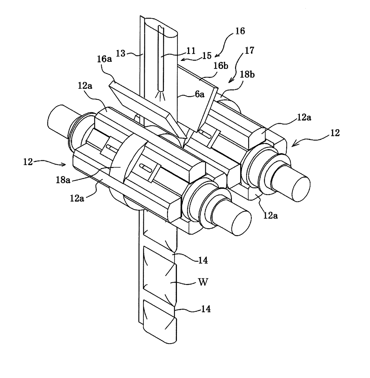
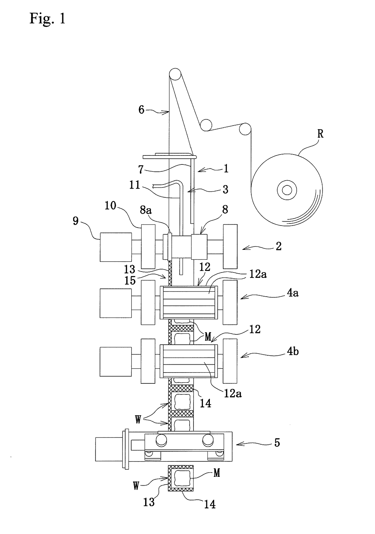
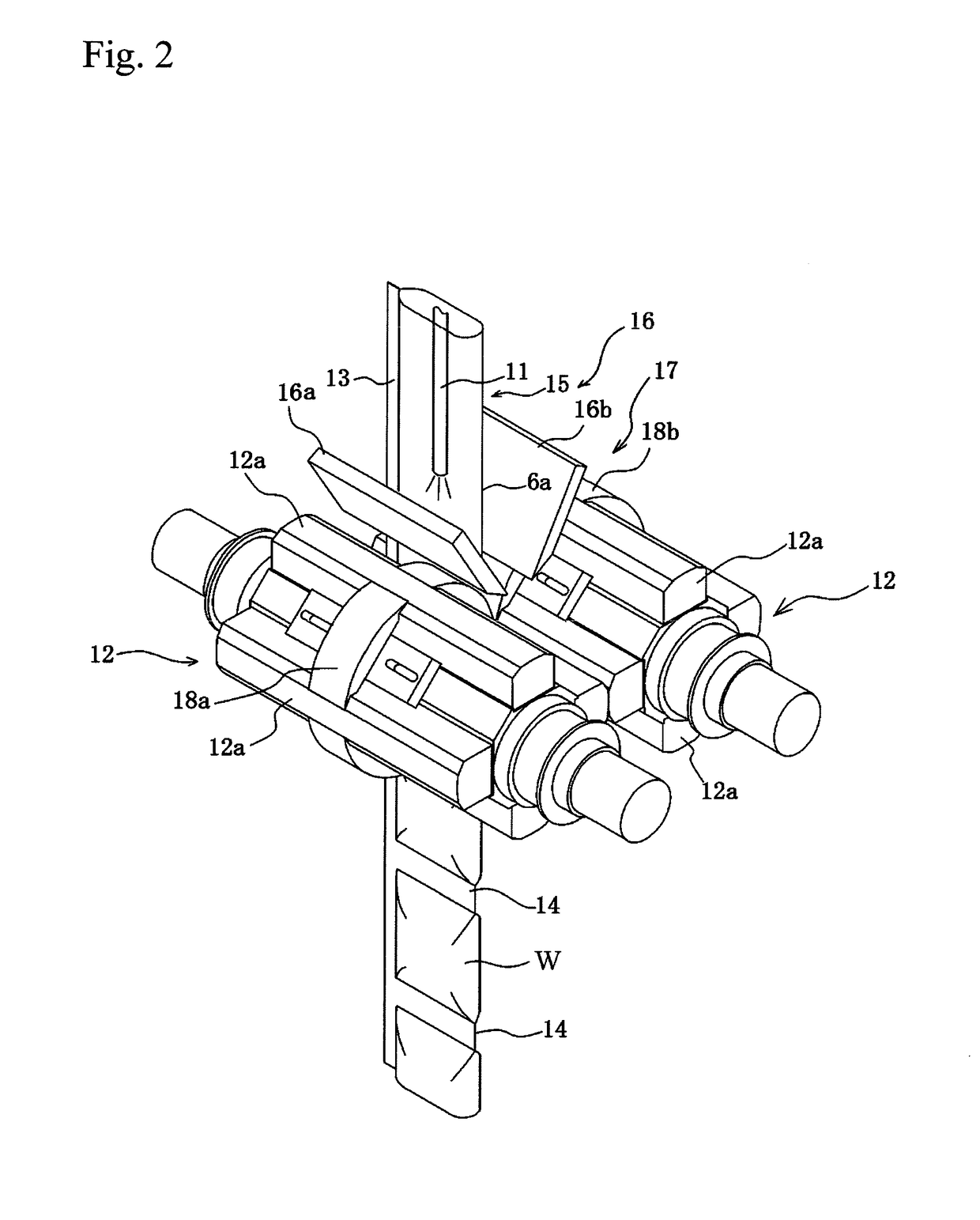
[0039]FIG. 1 is a schematic view illustrating a construction of a vertical fill packaging machine as an example of the fill packaging machine according to the invention.

[0040]In the vertical fill packaging machine, an elongated packaging film made of a laminate film by laminating a base film layer made, for example, from a biaxially oriented ethylene-vinyl alcohol copolymer resin or the like and a sealant layer made, for example, from a non-oriented ethylene-vinyl acetate copolymer resin or the like is folded in a widthwise direction so as to face the sealant layers to each other to overlap both side edge parts with each other while being run in its longitudinal direction, and many package bags are made from the packaging film and a packing material such as food and drink, seasonings, medicines, cosmetics and other liquidus, viscous or jelly fluidizing material is automatically f...


PUM

PropertyMeasurementUnit
heightaaaaaaaaaa
heightaaaaaaaaaa
widthaaaaaaaaaa

Abstract

In a method for forming a lateral sealed portion, a liquid packing material can be filled without biting bubbles, granulates and so on included in the liquid packing material into the lateral sealed portion. In a method for forming a lateral sealed portion with a pair of lateral sealing rolls after a packaging film fed and run is folded at its central portion and a vertical sealing is performed at their side edge parts to shape into a cylindrical form and a liquid packing material is filled into an inside of the cylindrically formed packaging film, at least a folded side part of the cylindrically formed packaging film is pushed with a pushing means arranged between heat sealing bars located at equal intervals in a circumferential direction of the lateral sealing roll and the lateral sealed portion is formed at a pushed position with the pair of lateral sealing bars.

Description

TECHNICAL FIELD[0001]This invention relates to a method for fill packaging a liquid packing material and a fill packaging machine utilizing such a method, and more particularly to a fill packaging method and fill packaging machine capable of blocking intrusion of a liquid packing material into a lateral seal portion.RELATED ART[0002]Recently, it is widely general to automatically fill and package a liquid packing material such as food and drink, seasonings, medicines, cosmetics or the like, a viscous material, powder, granulates or other material with a soft packaging film.[0003]In an automatically fill packaging machine for such a packing material, for example, as described in Patent Document 1, a packaging film having a laminated structure comprised of a uniaxially or biaxially oriented base film layer and a non-oriented sealant layer or a packaging film having a single layer structure of partly coating a heat-sensitive adhesive layer onto a base film layer is folded at a central ...

Claims


Application Information

Patent Timeline
Patent Type & Authority Applications(United States)
IPC IPC(8): B65B9/12B65B9/067B65B51/10
CPCB65B9/12B65B9/067B65B51/10B29C65/18B29C66/0326B29C66/1122B29C66/133B29C66/4312B29C66/4322B29C66/71B29C66/723B29C66/7234B29C66/7373B29C66/73921B29C66/81465B29C66/8167B29C66/83413B29C66/83513B29C66/8491B29C2793/009B65B51/306B29K2023/086B29K2023/083
Inventor HOSAKA, TOMOHISAYAJIMA, AKIRAFUKUDA, MICHIYA
Owner TAISEI LAMICK
Why Eureka
Try Eureka