
LCD element

a liquid crystal display and element technology, applied in the field of transmission/scattering type liquid crystal display devices, can solve the problems of low light utilization efficiency and large electrical power consumption, and achieve the effects of good optical properties, excellent properties, and high adhesion between liquid crystal layer and liquid crystal alignment films

Active Publication Date: 2017-08-31
NISSAN CHEM IND LTD
View PDF4 Cites 2 Cited by
  • Summary
  • Abstract
  • Description
  • Claims
  • Application Information

AI Technical Summary

Benefits of technology

The present invention provides a reverse device with good optical properties and adhesion between the liquid crystal layer and the liquid crystal alignment film, even in high-temperature, high-humidity, or light-exposure environments. The invention involves a specific compound and a liquid crystal alignment film that work together to enhance the vertical alignment property of the liquid crystal. The compound has a rigid structure and a polymerizable compound that enhances the stability of the vertical alignment property of the liquid crystal. The liquid crystal alignment film has a rigid structure or a photoreactive group that strengthens adhesion between the liquid crystal layer and the alignment film. The invention results in a reverse device with good optical properties that can maintain these properties for a long time.

Problems solved by technology

However, use of a polarizing plate lowers light utilization efficiency.
However, in a normal device, it is necessary to always apply a voltage in order to obtain a transmission state, and accordingly when it is used for an application which is mainly used in a transparent state, for example, when used for window glass, the electrical power consumption tends to be large.

Method used


Image

  • LCD element
  • LCD element
  • LCD element

Examples


synthesis example 1

[0197]E1 (3.50 g, 17.8 mmol), A2 (2.85 g, 7.22 mmol), B2 (1.92 g, 5.42 mmol) and C1 (0.83 g, 5.46 mmol) were mixed in PGME (27.3 g) and reacted at 40° C. for 30 hours, to obtain a polyamic acid solution (1) having a resin solid content concentration of 25 mass %. The number-average molecular weight (Mn) of this polyamic acid was 11,100, and the weight average molecular weight (Mw) was 46,300.

synthesis example 2

[0198]E2 (1.98 g, 7.91 mmol), A1 (3.05 g, 8.01 mmol), B1 (1.27 g, 4.81 mmol) and C1 (0.49 g, 3.22 mmol) were mixed in NMP (16.7 g) and reacted at 50° C. for 8 hours, and then, E1 (1.55 g, 7.90 mmol) and NMP (8.33 g) were added, followed by the reaction at 40° C. for 8 hours to obtain a polyamic acid solution (2) having a resin solid content concentration of 25 mass %. Mn of the polyamic acid was 21,000, and Mw was 62,700.

synthesis example 3

[0199]The polyamic acid solution (2) (30.0 g) obtained in Synthesis Example 2, was diluted to 6 mass % by adding NMP, and then, as imidization catalysts, acetic anhydride (3.90 g) and pyridine (2.40 g) were added, followed by the reaction at 50° C. for 4 hours. The reaction solution was poured into methanol (460 ml), and the obtained precipitate was collected by filtration. The precipitate was washed with methanol and dried at 60° C. under reduced pressure to obtain a polyimide powder (3). The imidization rate of the polyimide was 58%, Mn was 18,800, and Mw was 50,100.


PUM

PropertyMeasurementUnit
structureaaaaaaaaaa
side chain structureaaaaaaaaaa
optical rotation propertyaaaaaaaaaa

Abstract

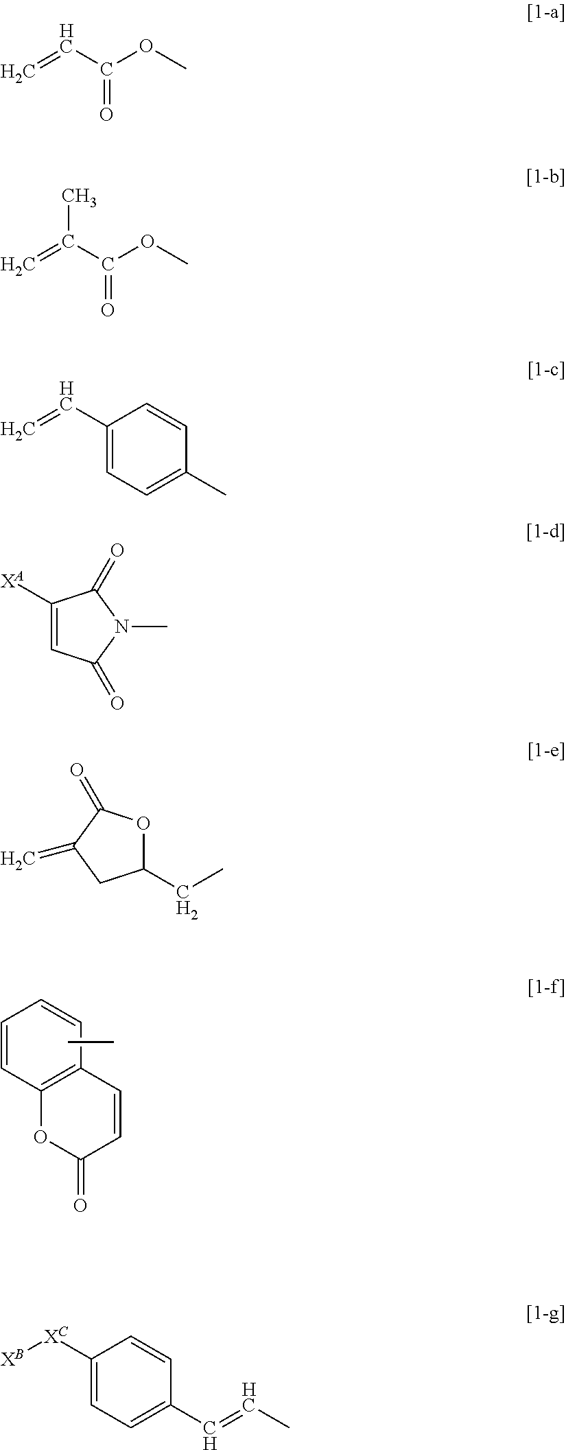
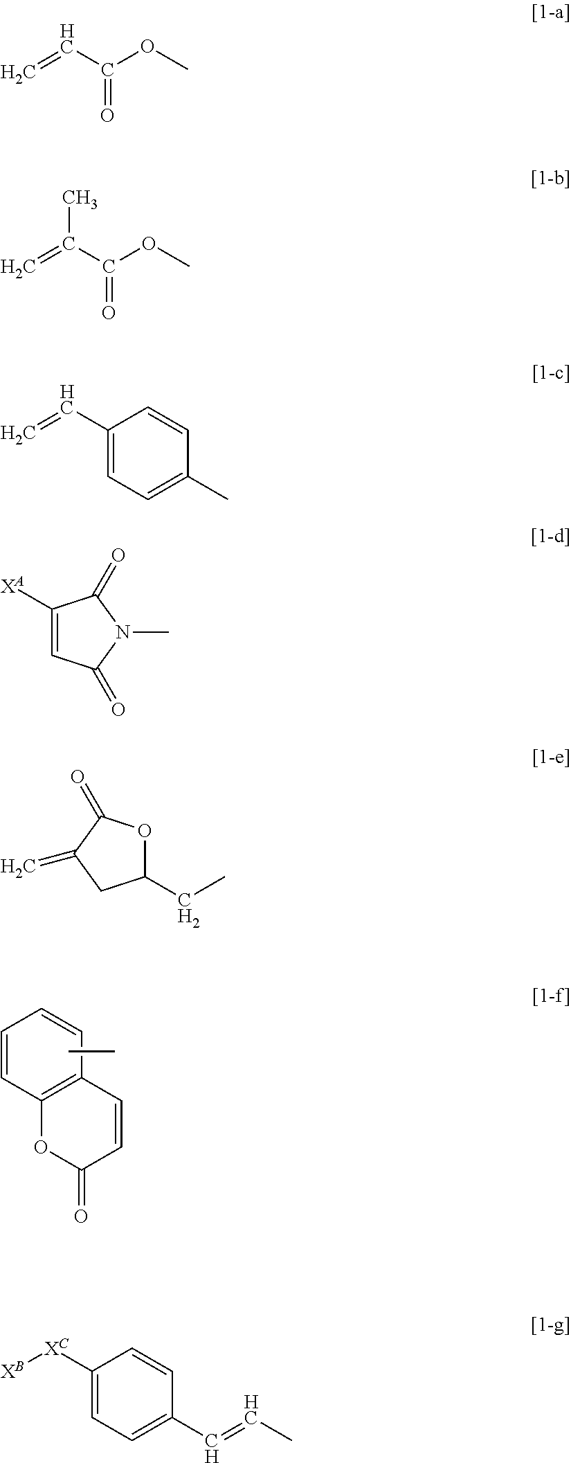
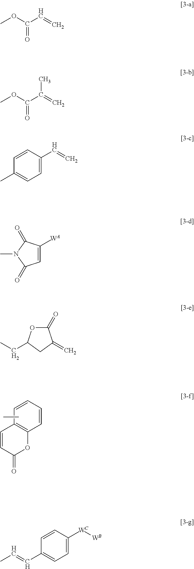
To provide a liquid crystal display device having excellent liquid crystal vertical alignment properties, good transparency when a voltage is applied and good scattering properties when no voltage is applied, and good adhesion with the liquid crystal layer. The liquid crystal display device has a liquid crystal layer formed by irradiating and curing with ultraviolet rays a liquid crystal composition containing a liquid crystal and a polymerizable compound disposed between a pair of substrates provided with electrodes, and at least one of the substrates is provided with a liquid crystal alignment film to vertically align a liquid crystal. The liquid crystal composition contains a compound represented by the formula [1], and the liquid crystal alignment film is obtained from a liquid crystal alignment treating agent containing a polymer having a side chain structure represented by the following formula [2-1] or formula [2-2], and a side chain structure represented by the following formula [3]:X1—X2—X3—X4—X5—X6x7pX8   [1](X1: the formula [1-a] to formula [1-g], etc., X2, X3, X4 and X6: a single bond, etc., X5 and X7: a benzene ring, etc., X8: a C1-18 alkyl group, etc.),(XA: H, etc., XB: a benzene ring, etc., XC: a C1-18 alkyl group, etc.),—Y1—Y2—Y3—Y4Y5nYt   [2-1](Y1, Y2 and Y3: a single bond, etc., Y4 and Y5: a benzene ring, etc., Y6: a C1-18 alkyl group, etc.,—Y7—Y8   [2-2](Y7: a single bond, Y8: a C8-22 alkyl group, etc.).

Description

TECHNICAL FIELD[0001]The present invention relates to a transmission / scattering type liquid crystal display device which is in a transparent state when no voltage is applied and in a scattering state when a voltage is applied.BACKGROUND ART[0002]As a liquid crystal display device employing a liquid crystal material, a TN (twisted nematic) mode liquid crystal display device is in practical use. In such a mode, light switching is carried out by utilizing the optical rotation property of a liquid crystal, and a liquid crystal display device in this mode requires use of a polarizing plate. However, use of a polarizing plate lowers light utilization efficiency.[0003]As a liquid crystal display device which achieves high light utilization efficiency without using a polarizing plate, a liquid crystal display device in which switching is conducted between a transmission state (also called a transparent state) and a scattering state of a liquid crystal may be mentioned, and a liquid crystal ...

Claims


Application Information

Patent Timeline
Patent Type & Authority Applications(United States)
IPC IPC(8): C08G73/10C09K19/30G02F1/1337C09K19/56
CPCC08G73/1078C09K19/56C09K19/3003G02F2001/133742C09K2019/3009C09K2019/301G02F1/133723C08G73/10G02F1/1334G02F1/1337C09K19/54C09K2019/0448C09K2323/02C09K2323/00G02F1/13345G02F1/133742
Inventor HOSAKA, KAZUYOSHIMIKI, NORITOSHIOMURA, HIROYUKIHASHIMOTO, JUN
Owner NISSAN CHEM IND LTD
Learn More