Battery charger with gauge-based closed-loop control

a battery charger and closed loop technology, applied in batteries, battery data exchange, instruments, etc., can solve the problems of introducing unnecessary complexity, additional system cost, and measurement accuracy of charger sensors, so as to prevent integral wind-up in the pid control scheme, reduce cost, and reduce the effect of precision

Inactive Publication Date: 2017-10-05
APPLE INC
View PDF16 Cites 7 Cited by
  • Summary
  • Abstract
  • Description
  • Claims
  • Application Information

AI Technical Summary

Benefits of technology

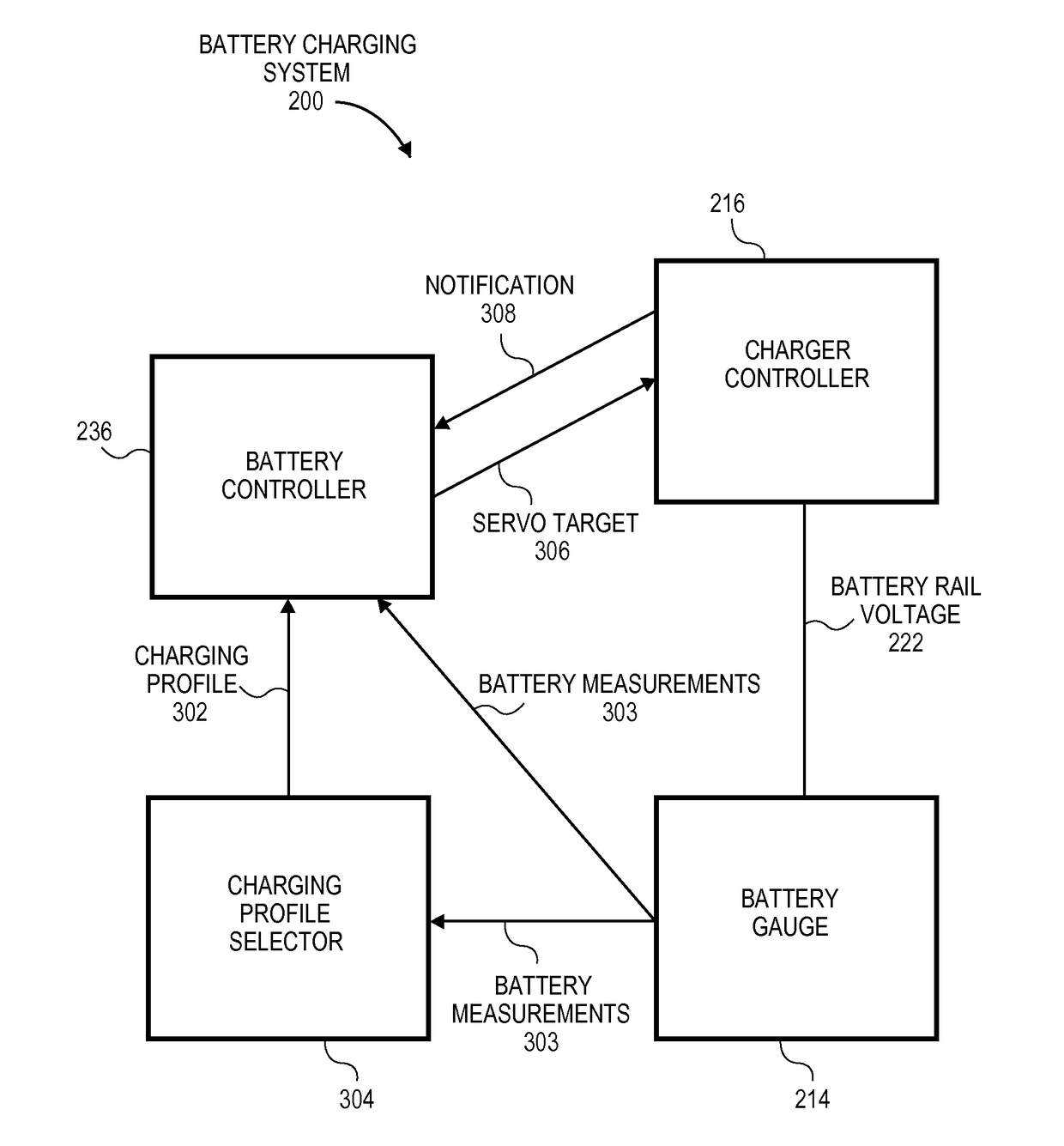
[0009]In an embodiment, a battery charging system and method prevents integral wind-up in the PID control scheme. The charger controller may be configured to provide a notification to the battery controller when any target other than the battery voltage rail is limiting the control of the power converter. For example, a method may include determining whether the second feedback control loop process is limited by an input voltage of the power converter, an input current of the power converter, or a duty cycle of the power converter. When the input voltage, the input current, or the duty cycle limits the second feedback control loop, the charger controller may send a notification to the battery controller. In response to the notification, the battery controller may be configured to discontinue its repeated determining or updating of the servo target to prevent a so-called windup condition.
[0010]In an embodiment, a battery charging system and method incorporates a lower cost, lower precision digital to analog conversion (DAC) circuit for producing the battery rail voltage set point, where such inaccuracy can be tolerated at the charger controller, because of the servo control being implemented by the battery controller and its accurate measurements. For instance, in one embodiment, the servo target variable may have “lower granularity”, i.e., it can take on fewer discrete values with greater spacing between adjacent values. Now, if it is desired to improve the accuracy of the charger control loop in such a case, the battery rail voltage set point may be dithered around the servo target, while the output of the DAC is low pass filtered to remove the frequency component caused by the dithering.
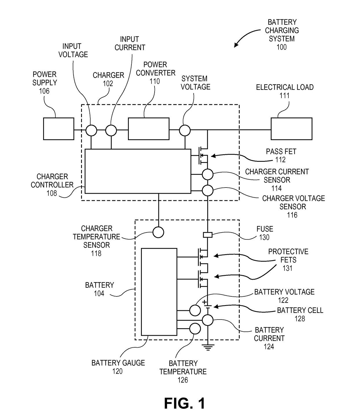
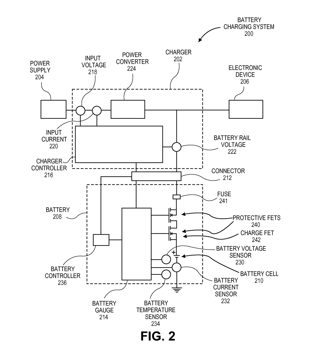
[0011]In an embodiment, a battery charging system and method as described above may eliminate redundancy in system components. For example, the pass field effect transistor (FET) 112 in the conventional charger 102 depicted in FIG. 1 can be removed, because a FET switch that is in line with the current path to the battery and that may be integrated in the battery can be coupled to be controlled by the battery controller. A method may include opening the FET switch circuit to disable charging of the battery, when the battery is fully charged. Thus, the battery charging system may not require an additional pass FET in the charger to disable the charging.

Problems solved by technology

First, since charger sensors provide measurements similar to the measurements made by battery sensors, the charger sensors represent a redundancy in system components.
For example, even if battery temperature sensor 118 provides an accurate measurement of battery temperature, it merely duplicates the measurement 126 that is already taken by battery gauge 120, resulting in additional system cost.
Second, the measurements made by the charger sensors may not accurately reflect the voltage and current through the battery cell 128 during charging.
Thus, typical charging systems may include redundant components that introduce unnecessary complexity and less accuracy into the battery charging control process.

Method used


Image

  • Battery charger with gauge-based closed-loop control
  • Battery charger with gauge-based closed-loop control
  • Battery charger with gauge-based closed-loop control

Examples


Embodiment Construction

[0022]Embodiments of the invention are battery charging systems for use in electronic devices powered by batteries. While some embodiments are described with specific regard to integration within portable electronic devices, the embodiments are not so limited, and certain embodiments may also be applicable to other uses. For example, one or more of the embodiments described below may be integrated within devices or apparatuses that are powered by batteries, regardless of whether the devices or apparatuses typically operate at a single location.

[0023]In various embodiments, description is made with reference to the figures. However, certain embodiments may be practiced without one or more of these specific details, or in combination with other known methods and configurations. In the following description, numerous specific details are set forth, such as specific configurations, dimensions, and processes, in order to provide a thorough understanding of the embodiments. In other insta...


PUM


Abstract

Systems and methods for power management are disclosed. In an embodiment, a battery charging system includes closed-loop control of a battery charger using a servo target based on measurements taken by a battery gauge.

Description

BACKGROUNDField[0001]Embodiments related to power management and battery charging systems, are disclosed. More particularly, an embodiment related to a battery charging system with closed-loop control of a battery charger using a servo target based on measurements taken by a battery gauge, is disclosed.Background Information[0002]FIG. 1 is a schematic view of a typical battery charging system. Battery charging system 100 may include a charger 102 connected to a battery 104. More specifically, a charger 102 may control the conversion of electrical power provided by an external power supply 106 and the delivery of the converted power to battery 104. A charger controller 108 may control a power converter 110 to deliver power directly to an electrical load 111 and to charge the battery, so as to not exceed the capabilities of power supply 106. The power may be delivered through a pass field effect transistor (FET) 112, and charger controller 108 may control the pass FET 112 to adjust a ...

Claims


Application Information

Patent Timeline
Patent Type & Authority Applications(United States)
IPC IPC(8): H02J7/00
CPCH02J7/0008H02J7/0077G01R31/3624G01R31/3842H02J7/00041H02J7/00712H02J7/00047
Inventor GREENING, THOMAS C.
Owner APPLE INC
Why Eureka
Try Eureka