Realtime optical method and system for detecting and classifying biological and non-biological particles

a biological and non-biological particle technology, applied in particle and sedimentation analysis, measurement devices, instruments, etc., can solve the problems of limited fielded lif based biological particle detectors, limited fielded lif based biological particle detection, and inability to detect lif based biological particle particles

Active Publication Date: 2017-11-02
HAMILTON ASSOCS
View PDF0 Cites 12 Cited by
  • Summary
  • Abstract
  • Description
  • Claims
  • Application Information

AI Technical Summary

Benefits of technology

[0011]When LIDS detection is used, differential scattering of vertically and horizontally polarized light is sensitive to the shape, refractive index and chiral content of particles, or more

Problems solved by technology

While these LIF based biological particle counter methods have shown to be useful early warning systems, they are not without limitations and significant room for improvement exists.
There are three primary limitations with LIF based biological particulate detection.
First, is their ability to detect single vegetative or spore type organisms.
Current fielded LIF based biological particle detectors are limited to detection of vegetative cell and spore aggregate particles or particles that contain numerous vegetative cells or spores per aerosol particle.
Second, their ability to discriminate biological from non-biological particles and to classify biological particle types, such as bacterial spores, mold spores, vegetative bacteria, viral aggregates, protein toxin aggregates, and fomite particles containing bacteria, viruses, or fungi is very limited.
With a minimum need for discrimination of biological from non-biological, the use of LIF based particle detection approaches are useful for discrimination from inorganic particles and non-fluorescing man-made particles but face serious limitations for particles that have been doped with

Method used


Image

  • Realtime optical method and system for detecting and classifying biological and non-biological particles
  • Realtime optical method and system for detecting and classifying biological and non-biological particles
  • Realtime optical method and system for detecting and classifying biological and non-biological particles

Examples


Embodiment Construction

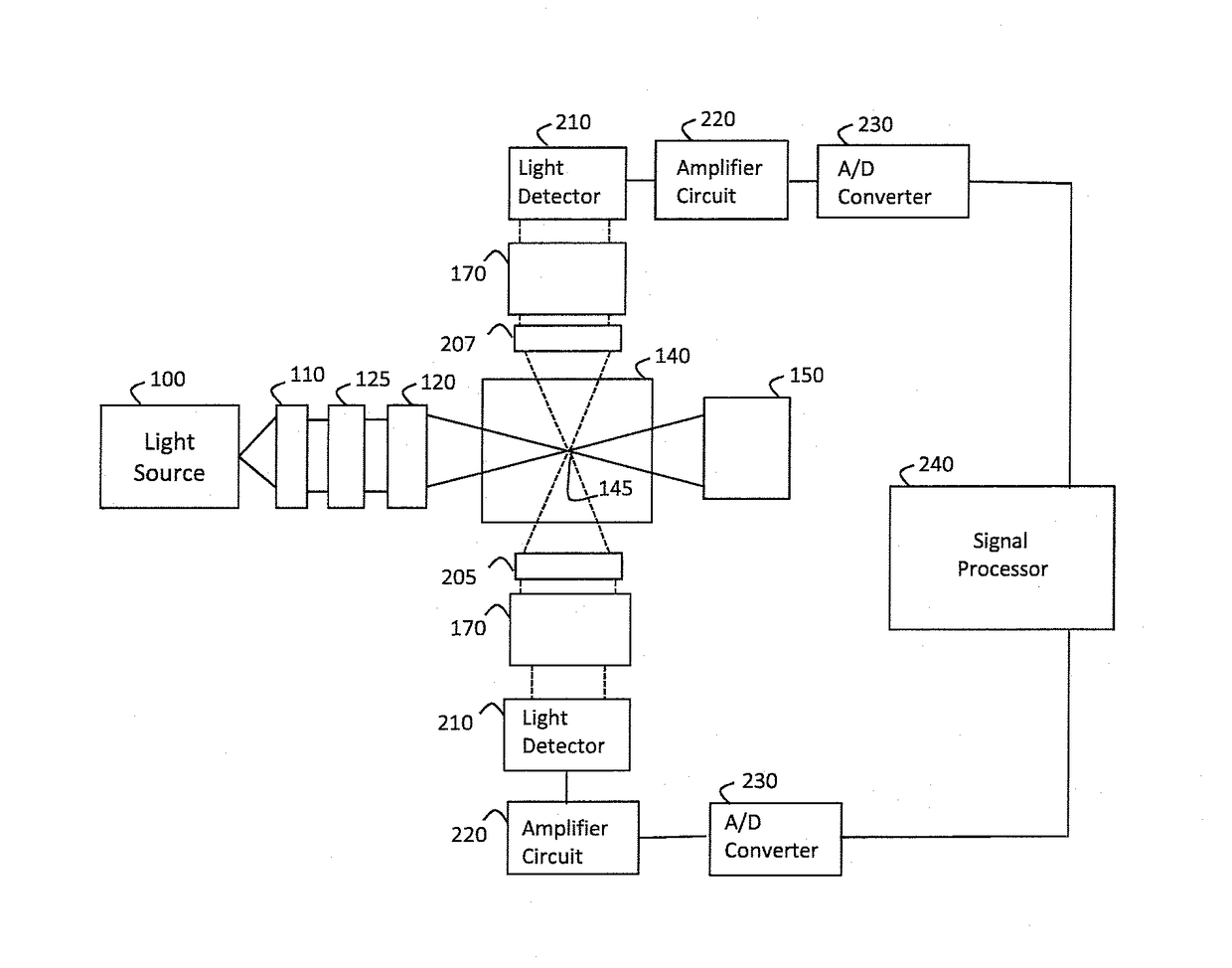
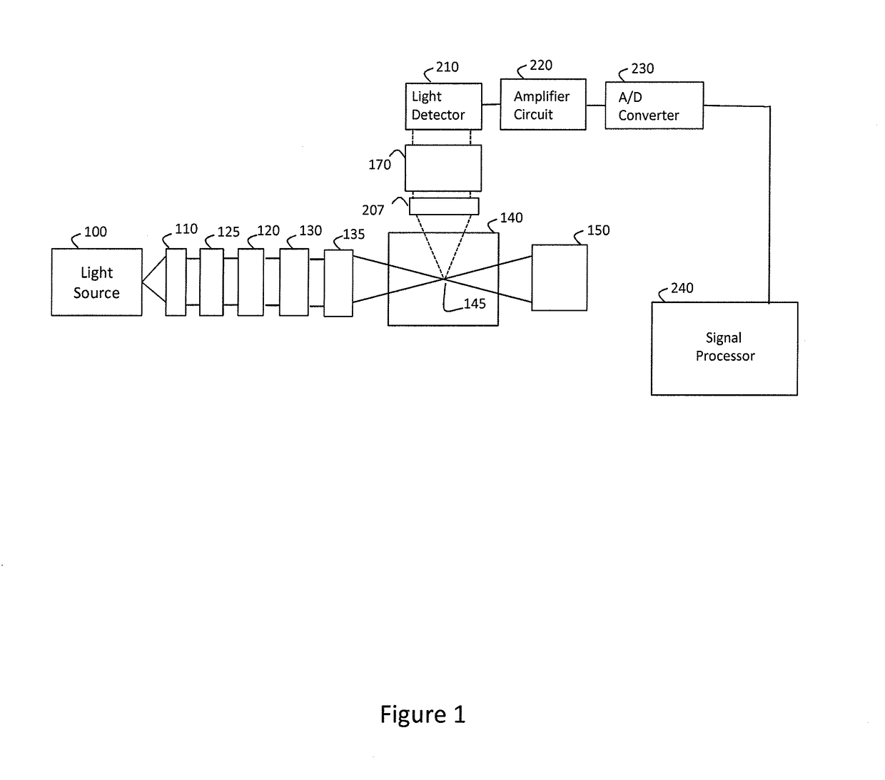
[0030]The preferred forms of the presented invention will now be described with reference to FIGS. 1-13. The appended claims are not limited to the preferred forms and no term and / or phrase used herein is to be given a meaning other than its ordinary meaning unless it is expressly stated otherwise. The use of like reference numerals indicate the same component and / or feature except when otherwise indicated.

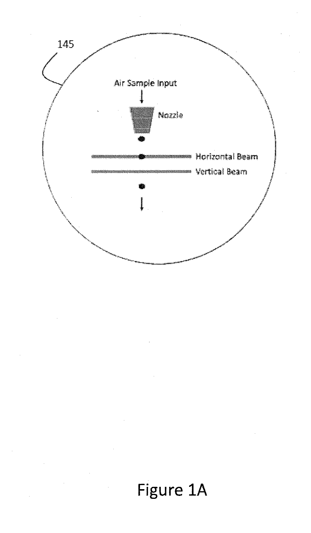
[0031]The preferred forms of the present invention relate to enhanced methods, apparatuses and systems for the detection and classification of biological and non-biological particulates in a real-time manner. The various detection schemes exploit one physical phenomena which involves the interaction of light with a single aerosol particle (i.e., polarized elastic scattering). A second physical phenomena which involves the interaction of light with a single aerosol particle may be used (i.e., fluorescence). In addition to these optical phenomena (i.e., polarized elastic scattering ...


PUM


Abstract

Methods, apparatuses, and systems for detecting and classifying individual airborne biological and non-biological particles, in real time, based on particle size and polarized elastic scatter. Auto-fluorescence content may also be used along with particle size and polarized elastic scatter for further orthogonal classification. With polarized elastic scattering, the degree of linear or circular depolarization produced from particle morphology, refractive index, internal asymmetric structures and molecular optical activity can be used for classifying individual airborne particles. Alternatively, circular intensity differential scattering (CIDS) or linear intensity differential scattering (LIDS) can be used to discriminate individual particles.

Description

FIELD OF INVENTION[0001]This invention pertains generally to aerosol analyzers and more specifically to optical analyzers for the real-time detection and classification of airborne biological and non-biological particles.BACKGROUND OF INVENTION[0002]There has been significant progress over the last 15 years in the development of both methods and systems that provide real-time detection and classification of airborne biological and non-biological particles. Most of the methods and systems have been based on optical approaches that utilize both particle sizing and laser induced fluorescence (LIF) to discriminate biological from non-biological particles. These methods have included illumination approaches using various wavelengths specific towards exciting endogenous fluorophores commonly found in biological particles. LIF based approaches have also included multiple excitation sources operating at different wavelengths for improved classification. Other approaches have included laser ...

Claims


Application Information

Patent Timeline
IPC IPC(8): G01N15/14G01N15/02G01N15/00
CPCG01N15/1434G01N2015/0065G01N15/1429G01N15/0211G01N2015/0046G01N15/1459G01N2021/217G01N2015/1006
Inventor SILCOTT, DAVID B.
Owner HAMILTON ASSOCS
Why Eureka
Try Eureka