Cooling Arrangement for an Energy Storage Device

a technology of energy storage device and cooling arrangement, which is applied in the direction of battery pack, cell components, sustainable manufacturing/processing, etc., can solve the problems of limiting the effectiveness of external cooling, increasing the cost of battery pack, and reducing battery efficiency, so as to reduce the thermal resistance between the cell heat source and the heat sink, and the heat distribution within the cell is more uniform, the effect of high thermally conductive pathway

Active Publication Date: 2017-11-09
ROBERT BOSCH GMBH +1
View PDF2 Cites 11 Cited by
  • Summary
  • Abstract
  • Description
  • Claims
  • Application Information

AI Technical Summary

Benefits of technology

[0009]In some aspects, a pouch cell includes an electrode assembly that is sealed within a flexible metal foil laminate cell housing along with an electrolyte to form an energy storage unit. The electrode assembly is a “stacked” electrode assembly that includes a series of stacked positive electrode plates alternating with negative electrode plates and separated by an intermediate separator plates. In addition, the pouch cell includes current collectors that form an electrical connection with the electrode plates and also provides a thermal conduction pathway for conducting heat from the electrode plates. The current collectors allow passage of current generated in the electrode assembly to pass through the current collector and out of the cell to a terminal, and also allow thermal conduction of heat generated in the electrode assembly to pass through the current collector and out of the cell to an external, thermally-conductive plate.
[0010]Advantageously, the internal current collectors of the cell are used to extract heat directly from the electrodes and transfer it via a thermally conductive path to the exterior of the cell. The exterior conductor portion of the current collector is in direct contact with the thermally conductive plate, providing a high thermally conductive pathway between the electrodes (heat source) to the cooling medium (heat sink). As a result, thermal resistance between the cell heat source and the heat sink is reduced, and heat distribution within the cell is more uniform relative to some conventional cells.

Problems solved by technology

Such cooling methods may present problems, which include, but are not limited to, a) increased battery pack cost since liquid cooling systems are expensive due to costs associated with driving fluids through the system; b) decreased battery efficiency pack since, in an electric vehicle application, energy from the cells is used to cool the cells, which in turn may generate more heat which needs to be removed; and c) cell thermal performance may limit the effectiveness of external cooling since cells may have a high thermal gradient internally due to the inefficient heat path to the exterior of the cell.
Moreover, some cells may have degraded performance when operating in very cold conditions, such as can occur during winter months in northern climates.

Method used


Image

  • Cooling Arrangement for an Energy Storage Device
  • Cooling Arrangement for an Energy Storage Device
  • Cooling Arrangement for an Energy Storage Device

Examples


Embodiment Construction

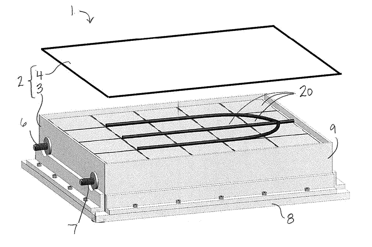
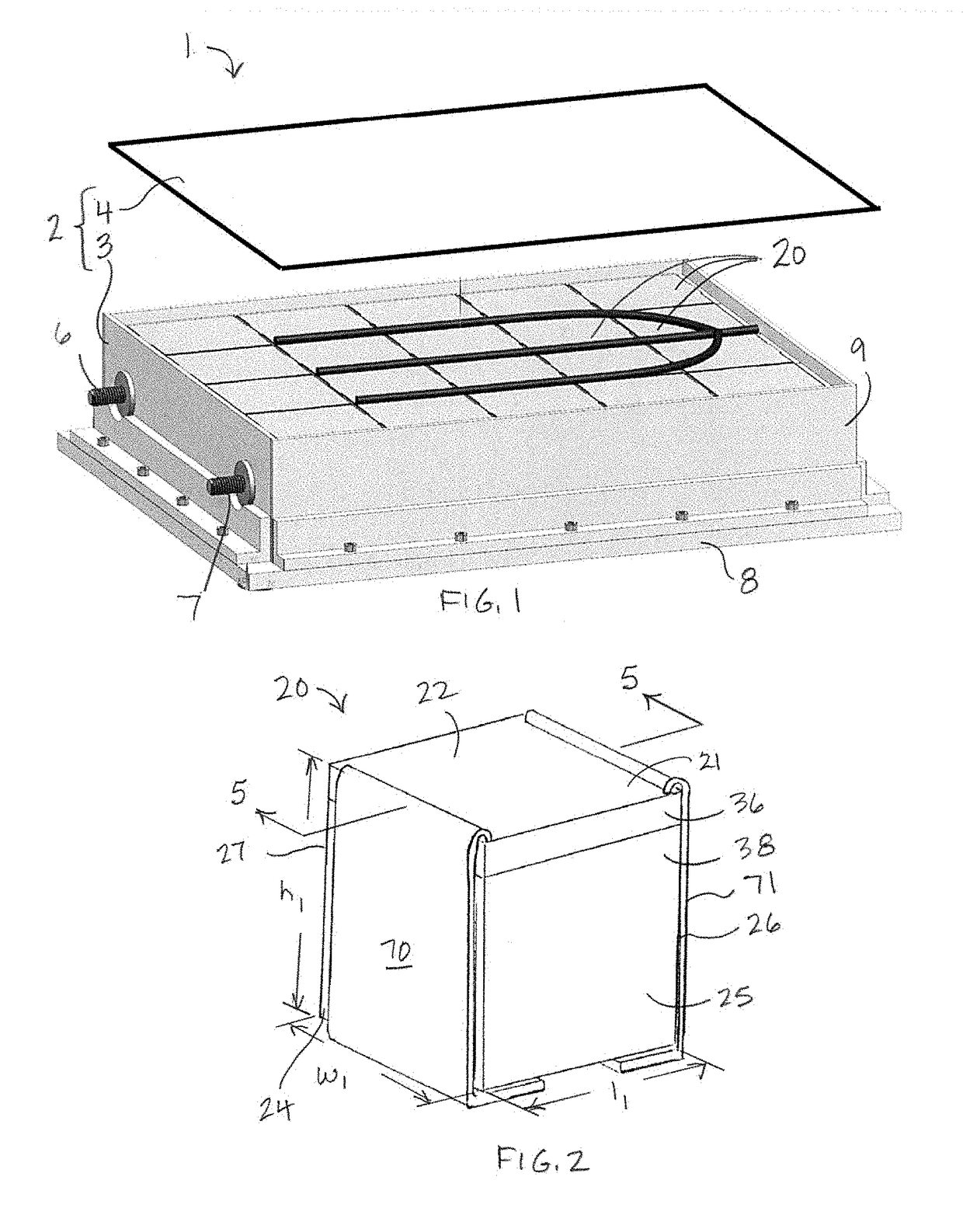
[0026]Referring to FIGS. 1-2, a battery pack 1 used to provide electrical power includes electrochemical cells 20 that are electrically interconnected and stored in an organized manner within a battery pack housing 2. The battery pack housing 2 includes a container portion 3 and a detachable lid 4. The container portion 3 includes a base 8 and a sidewall 9 that encloses a peripheral edge of the base 8. The base 8 serves as a heat sink or a heat source. To this end, the base 8 is formed of a thermally conductive material. In some embodiments, an inward-facing (e.g., cell-supporting) surface of the base 8 is formed of or coated with an electrically isolating material. In addition, the base 8 may include fluid channels (not shown) configured to permit a flow of cooling or heating fluid through the base 8. For purposes of illustration, only the cooling function of the base 8 will be described herein. In use, the lid 4 is secured to an upper edge of the sidewall 9 so as to close the open...


PUM

PropertyMeasurementUnit
thicknessaaaaaaaaaa
flexibleaaaaaaaaaa
dimensionaaaaaaaaaa

Abstract

A battery pack includes a thermally conductive plate that can be cooled or heated, and an array of electrochemical cells. The cells include a stacked or rolled arrangement of electrode plates, and a current collector disposed in the battery cell that forms an electrical connection with the electrode plates and provides a thermal conduction pathway for conducting heat from the electrode plates to the thermally conductive plate.

Description

BACKGROUNDField of the Invention[0001]The present invention relates to a battery cell that includes a stacked or rolled arrangement of electrode plates, and a current collector disposed in the battery cell that forms an electrical connection with the electrode plates and provides a thermal conduction pathway for conducting heat from the electrode plates to an external cooling plate.Description of the Related Art[0002]Battery packs provide power for various technologies ranging from portable electronics to renewable power systems and environmentally friendly vehicles. For example, hybrid electric vehicles (HEV) use a battery pack and an electric motor in conjunction with a combustion engine to increase fuel efficiency. Battery packs are formed of a plurality of battery modules, where each battery module includes several electrochemical cells. The cells are arranged in two or three dimensional arrays and are electrically connected in series or in parallel. Likewise, the battery module...

Claims


Application Information

Patent Timeline
Patent Type & Authority Applications(United States)
IPC IPC(8): H01M10/613H01M10/6551H01M2/30H01M10/625H01M2/02H01M10/6554H01M2/10H01M2/26H01M50/105H01M50/119H01M50/124H01M50/136H01M50/211H01M50/529H01M50/533H01M50/54H01M50/548H01M50/553
CPCH01M10/613H01M2/30H01M2/26H01M10/625H01M2/0275H01M2002/0297H01M10/6551H01M2/1077H01M10/6554H01M2220/20H01M2/0262H01M10/0413H01M10/0472H01M10/6553H01M10/647H01M10/654H01M10/6555Y02E60/10H01M50/529H01M50/54Y02P70/50H01M50/105H01M50/124H01M50/136H01M50/533H01M50/548H01M50/211H01M50/553H01M50/119H01M50/20H01M50/543H01M50/531H01M50/131H01M50/502
Inventor SCHOENHERR, ROBERTKOTIK, MARK
Owner ROBERT BOSCH GMBH
Why Eureka
Try Eureka