

D1563 radiation curable secondary coating for optical fibers
- Summary
- Abstract
- Description
- Claims
- Application Information
AI Technical Summary
Benefits of technology
Problems solved by technology
Method used
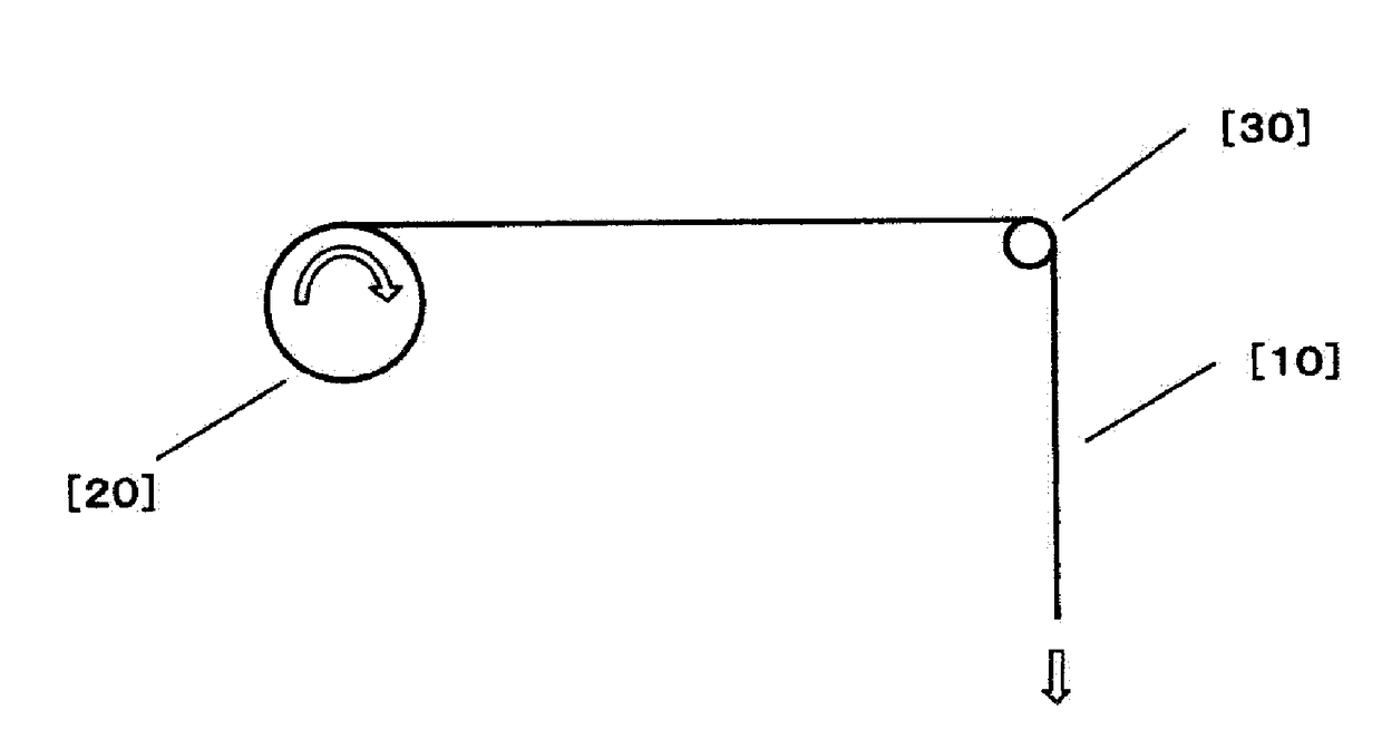
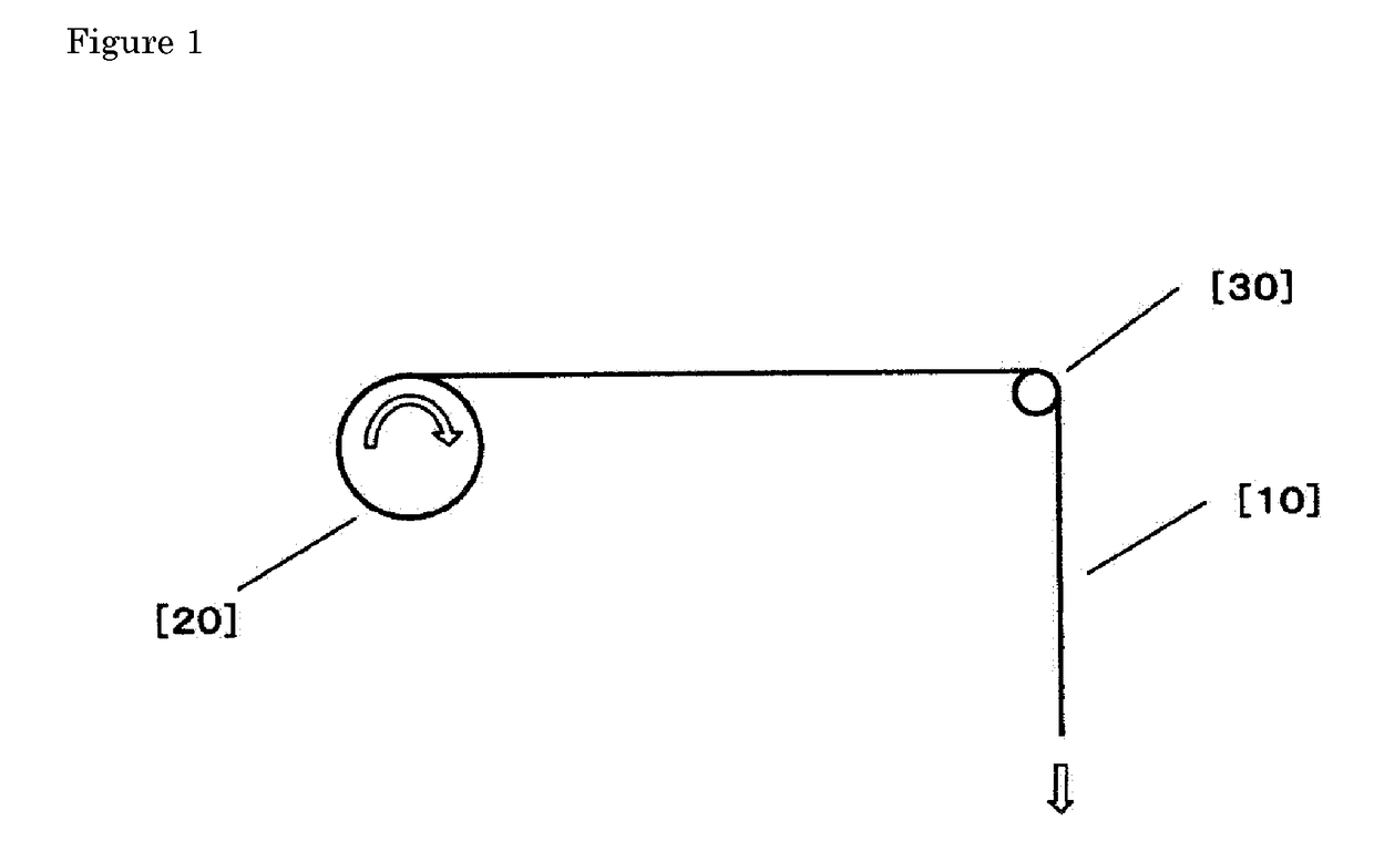
Image

Examples
working examples
[0086]Next, the present invention will be explained in detail by giving working examples, but the present invention is not limited to these working examples in any way.
production example 1
Synthesis of urethane (meth)acrylate (A) 1
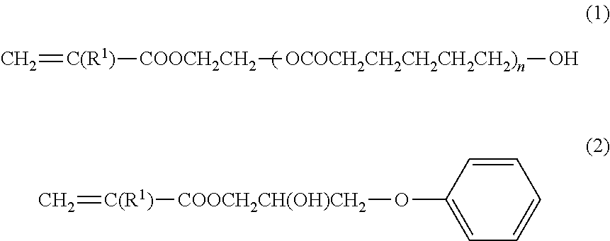
[0087]0.24 g of 2,6-di-t-butyl-p-cresol, 355 g 2,4-tolylene diisocyanate, and 408 g polypropylene glycol with a number average molecular weight of 400 g / mol were added to a reaction vessel equipped with an agitator. After 0.80 g dibutyltin dilaurate was added gradually under cooling, agitation was performed for 1 hour at a liquid temperature of 65-75° C. After this, 237 g hydroxyethyl acrylate was dripped in while controlling the liquid temperature to 80° C. or below, after which the agitation was continued for 2 hours at a liquid temperature of 70-75° C., and the reaction was stopped when the residual isocyanate was 0.1 mass % or below. The obtained (meth)acrylate (A) is referred to as “UA1.”
production example 2
Synthesis of urethane (meth)acrylate (A) 2
[0088]0.24 g of 2,6-di-t-butyl-p-cresol, 220 g of 2,4-tolylene diisocyanate, and 632 g of polypropylene glycol with a number average molecular weight of 1000 g / mol were added to a reaction vessel equipped with an agitator. After 0.27 g dibutyltin dilaurate was added gradually under cooling, agitation was performed for 1 hour at a liquid temperature of 65-75° C. After this, 147 g hydroxyethyl acrylate was dripped in while controlling the liquid temperature to 80° C. or below, after which the agitation was continued for 2 hours at a liquid temperature of 70-75° C., and the reaction was stopped when the residual isocyanate was 0.1 mass % or below. The obtained (meth)acrylate (A) is referred to as “UA2.”
PUM
| Property | Measurement | Unit |
|---|---|---|
| Temperature | aaaaa | aaaaa |
| Fraction | aaaaa | aaaaa |
| Fraction | aaaaa | aaaaa |
Abstract
Description
Claims
Application Information