Photoacoustic computed tomography with an acoustic reflector

a computed tomography and acoustic reflector technology, applied in the field of photoacoustic computed tomography with an acoustic reflector, can solve the problems of not being as easily integrated with ultrasound systems, specialized full-scale, and relatively expensiv

Active Publication Date: 2017-12-28
WASHINGTON UNIV IN SAINT LOUIS
View PDF3 Cites 7 Cited by
  • Summary
  • Abstract
  • Description
  • Claims
  • Application Information

AI Technical Summary

Problems solved by technology

To obtain high-quality images, specialized full-ring transducer arrays may be used for full-view detection, but may be relatively expensive compared to linear arrays and may not be as easily integrated with ultrasound systems.
While commercial linear arrays are readily available, they often suffer from limited-view problems, and the detectable structure is sensitive to the orientations and positions of the probes.
For instance, acoustic waves traveling at a grazing angle to the transducer surface are typically difficult to detect.
However, these methods require time-consuming mechanical scanning.
However, systems making use of this method still include circular scanning with a single-element transducer, and modeling the backscattered signals may be complicated.
Limited-view problems may also be ameliorated using advanced image reconstruction algorithms; however, these image reconstruction methods are typically computationally intensive and time-consuming.
In addition, it has been proposed to use acoustic reflectors at either end of, and perpendicular to, a linear array transducer to generate an infinitely wide virtual array, but this method has only been demonstrated in simulations to date

Method used


Image

  • Photoacoustic computed tomography with an acoustic reflector
  • Photoacoustic computed tomography with an acoustic reflector
  • Photoacoustic computed tomography with an acoustic reflector

Examples


example 1

Small-Animal Imaging

[0055]Small-animal whole-body imaging using the system may use a 512-element full-ring transducer array. Excitation was provided by a Ti-sapphire laser tunable from about 700 nm to about 900 nm. With the combination of a conical lens and an optical condenser, a ring-shaped light beam was projected around the animal body at an about 60° incident angle. The thickness of the light ring was about 5 mm, and the diameter may be sized to accommodate the cross-sectional diameter (about 2 cm) of the animal. The maximum light intensity at the surface of the animal was about 15 mJ / cm2, which is below the ANSI safety limit at the chosen wavelength.

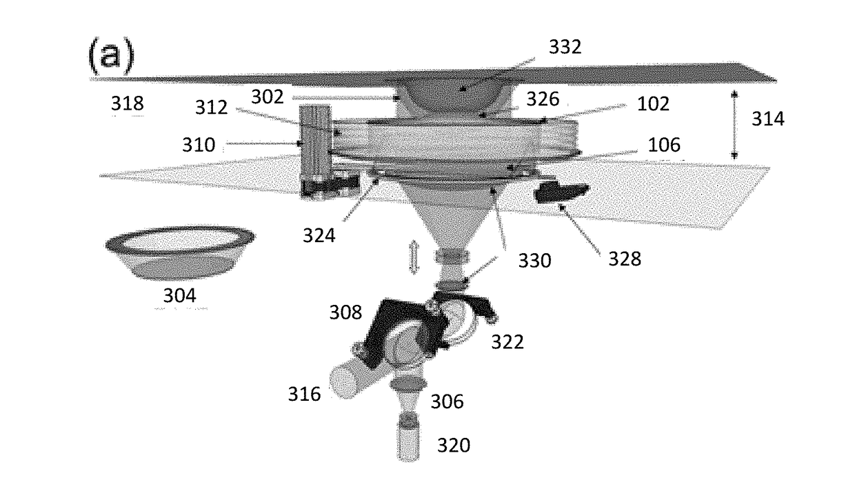
[0056]To cover a broad range of applications, two system configurations as illustrated in FIGS. 5A and 5B and FIGS. 6A and 6B were used for trunk and brain imaging. In FIGS. 5A and 5B, the system elements include 502: animal holder; 518: breathing mask; 504: heated coupling medium; 514: conical lens; 516: laser beam; 706: metal fra...

example 2

Linear Array

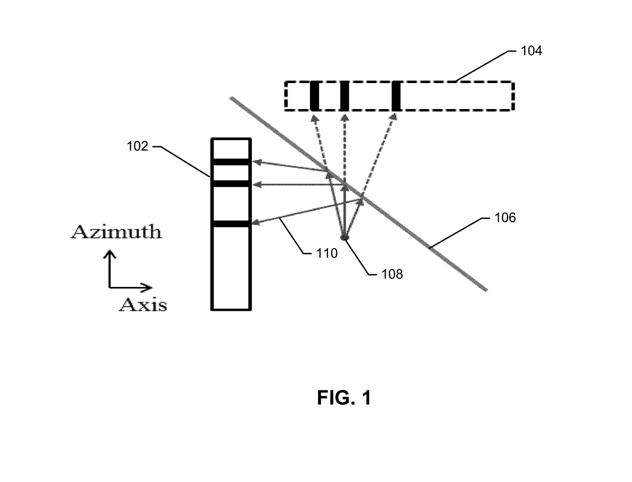
[0062]A commercially obtained Philips linear array was operated in B-mode to collect photoacoustic signals, a 45-degree acoustic reflector (glass) was used to form a virtual array, and a laser beam aligned orthogonally to the drawing illuminated the water tank from the top (not shown in the figure).

[0063]In addition to the conventional linear array, a quarter inch thick borosilicate glass plate (8476K72, McMaster-Carr, Los Angeles, Calif.) functioned as an acoustic reflector to form a virtual linear array. The glass plate had a sound speed of 5790 m / s for longitudinal waves and 3420 m / s for shear waves. When the angle of incidence was greater than 26° (the critical angle for Rayleigh surface waves in borosilicate glass), the incident PA waves were completely reflected without distortion. For angles of incidence between 0° (perpendicular incidence) and a longitudinal critical angle of 14°, about 80% of the pressure of the incident PA waves reflected with no phase change, ...

example 3

Hair Phantom

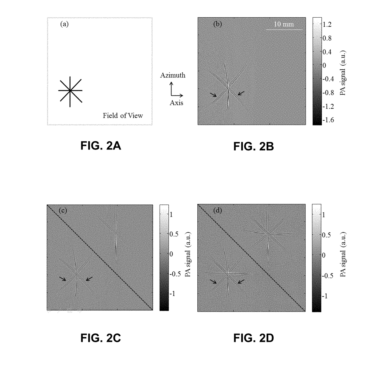
[0066]To experimentally validate the reconstruction technique using the system described in Example 2, a phantom consisting of four human hairs was imaged using the system of Example 2 at different angles on the azimuth-axis plane (FIG. 2A) and the phantom image was reconstructed under different conditions. FIGS. 2A, 2B, 2C, and 2D show PAT images of a hair phantom. The dashed-line indicates the position of the acoustic reflector. FIG. 2B is an image acquired without the presence of the acoustic reflector. FIG. 2C is an image acquired with the presence of the reflector—as indicated by the dashed-line—but reconstructed without incorporating the virtual array. The linear array was unable to detect the horizontal hair, because the cylindrical PA wavefront from that hair propagated in the azimuth (vertical) direction and hence missed the physical array unless reflected using the acoustic reflector. The reconstruction incorporating data from the virtual array successfully ove...


PUM


Abstract

Systems and methods for improving limited-view photoacoustic tomography using an acoustic reflector are described. In particular, an acoustic reflector and ultrasonic transducer array are integrated to provide a virtual array that enhances the field of view of the ultrasonic transducer array, thereby improving the quality of photoacoustic tomography images obtained using the systems and methods described herein.

Description

CROSS-REFERENCE TO RELATED APPLICATIONS[0001]This application is a 35 U.S.C. §371 national stage application of PCT Application No. PCT / US2014 / 065195, filed Nov. 12, 2014, which claims the benefit of U.S. Provisional Application No. 61 / 902,918 filed on Nov. 12, 2013, both of which are incorporated herein by reference in their entirety.GOVERNMENTAL RIGHTS IN THE INVENTION[0002]This invention was made with government support under Grant No. R01 EB016963 (NIH). The government has certain rights in the invention.FIELD OF THE INVENTION[0003]The invention generally relates to systems and methods for improving limited-view photoacoustic tomography with an acoustic reflector.BACKGROUND OF THE INVENTION[0004]Photoacoustic tomography (PAT) provides high-resolution biomedical images beyond the optical diffusion limit by combining optical absorption contrast and ultrasonic spatial resolution. To obtain high-quality images, specialized full-ring transducer arrays may be used for full-view detect...

Claims


Application Information

Patent Timeline
Patent Type & Authority Applications(United States)
IPC IPC(8): A61B5/00A61B8/00
CPCA61B5/0095A61B2562/0204A61B5/0042A61B8/4483A61B2503/40A61B8/4245
Inventor WANG, LIHONGHUANG, BINXIA, JUNMASLOV, KONSTANTINANASTASIO, MARK
Owner WASHINGTON UNIV IN SAINT LOUIS
Why Eureka
Try Eureka