
Clock Computing Machines

a computing machine and clock technology, applied in the field of clock computing machines, can solve the problems of huge vulnerabilities in our internet infrastructure, the difficulty of scientists building a comprehensive vaccine for the aids virus, and the diversity of the population, so as to achieve computationally fast and easy hardware construction, and the effect of promising capabilities

Active Publication Date: 2018-01-04
AEMEA
View PDF3 Cites 6 Cited by
  • Summary
  • Abstract
  • Description
  • Claims
  • Application Information

AI Technical Summary

Benefits of technology

This patent describes a method for generating random clock machines that can be used for cryptographic purposes. These machines are unique and can perform complex functions that would be difficult for predators or hackers to attack. The method is based on the idea that every bacteria organism is unique in the way it can build proteins to disable antibiotics. The clock machines described in the patent can also be used to create virtual machines that can improve the speed and efficiency of cryptographic methods. Overall, this innovation has practical applications in the field of cryptography and computer security.

Problems solved by technology

The uniqueness of the physical instantiation follows a biological principle whereby a population that exhibits diversity can be far more challenging for predators or a sentient manipulator of that population.
As another example of population diversity, the variability of the retrovirus (in particular, AIDS) and its ability to quickly evolve has made it far more difficult for scientists to construct a comprehensive vaccine for the AIDS virus.
This weakness in current computing systems creates huge vulnerabilities in our Internet infrastructure.
The Mirai attack and other recent cyber attacks have triggered an urgent alarm that developing new machines, methods and procedures resistant to malware infection is a critical issue for industry and for U.S. infrastructure such as air traffic control, the electrical grid and the Internet.
These two group properties enable prime clock machines to compute in parallel, while computers built from gates do not have this favorable property.
This means that the gate-based computers used in the prior art have physical and mathematical limitations on the extent to which the prior art gate-based computers can be parallelized.

Method used


Image

  • Clock Computing Machines
  • Clock Computing Machines
  • Clock Computing Machines

Examples


example

[0122]This example demonstrates 2-bit multiplication with prime clock sums, computed with machine procedure 2. In table 6, for each u∈{0, 1}2 and each l∈{0, 1}2, the product u*l is shown in each row, whose 4 columns are labelled by 3, 2, 1 and 0. With input i of 4 bits (i.e., u concatenated with l), the output of the 2-bit multiplication is a 4-bit string 3(i) 2(i) 1(i) 0(i), shown in each row of table 6.

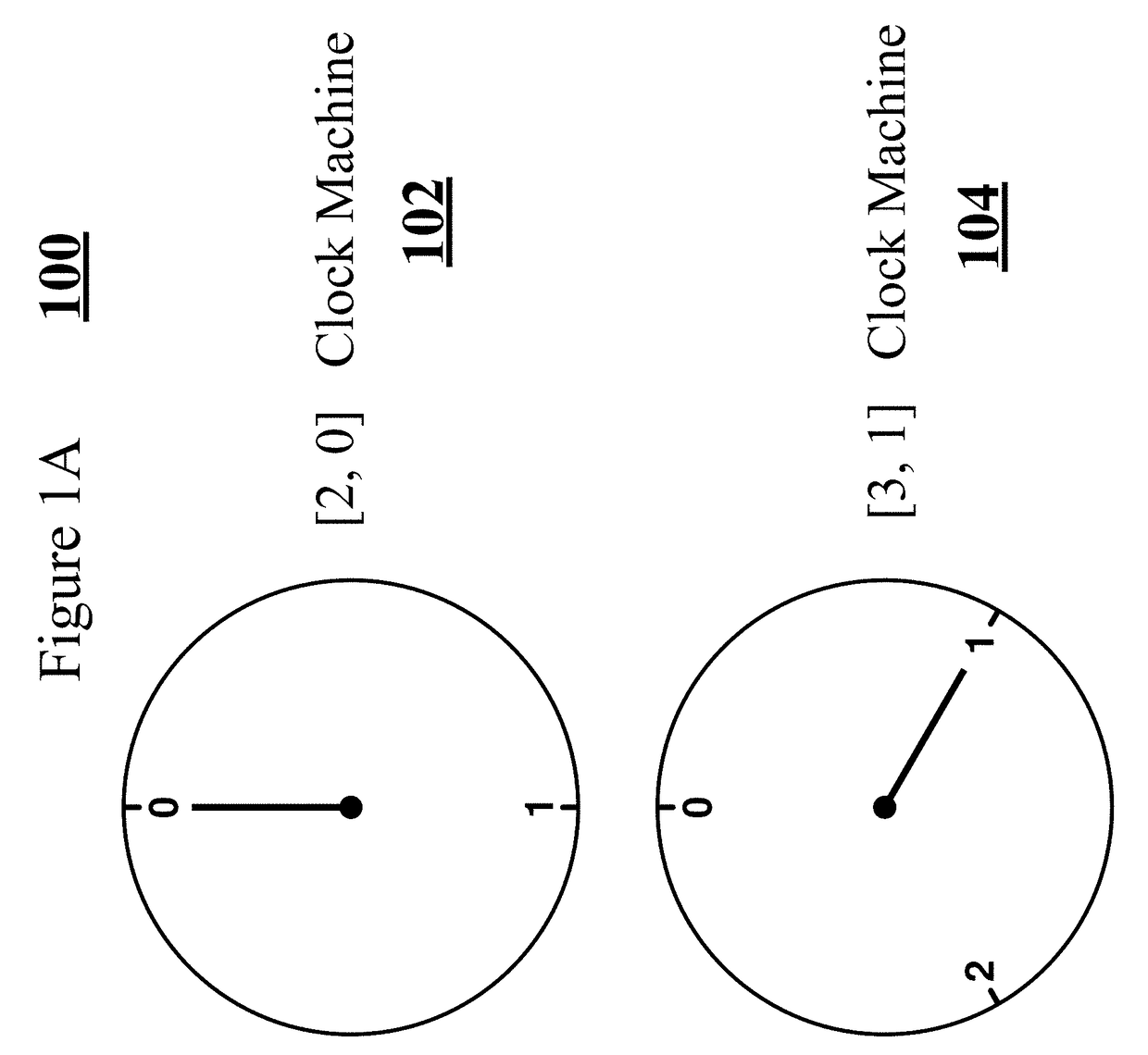
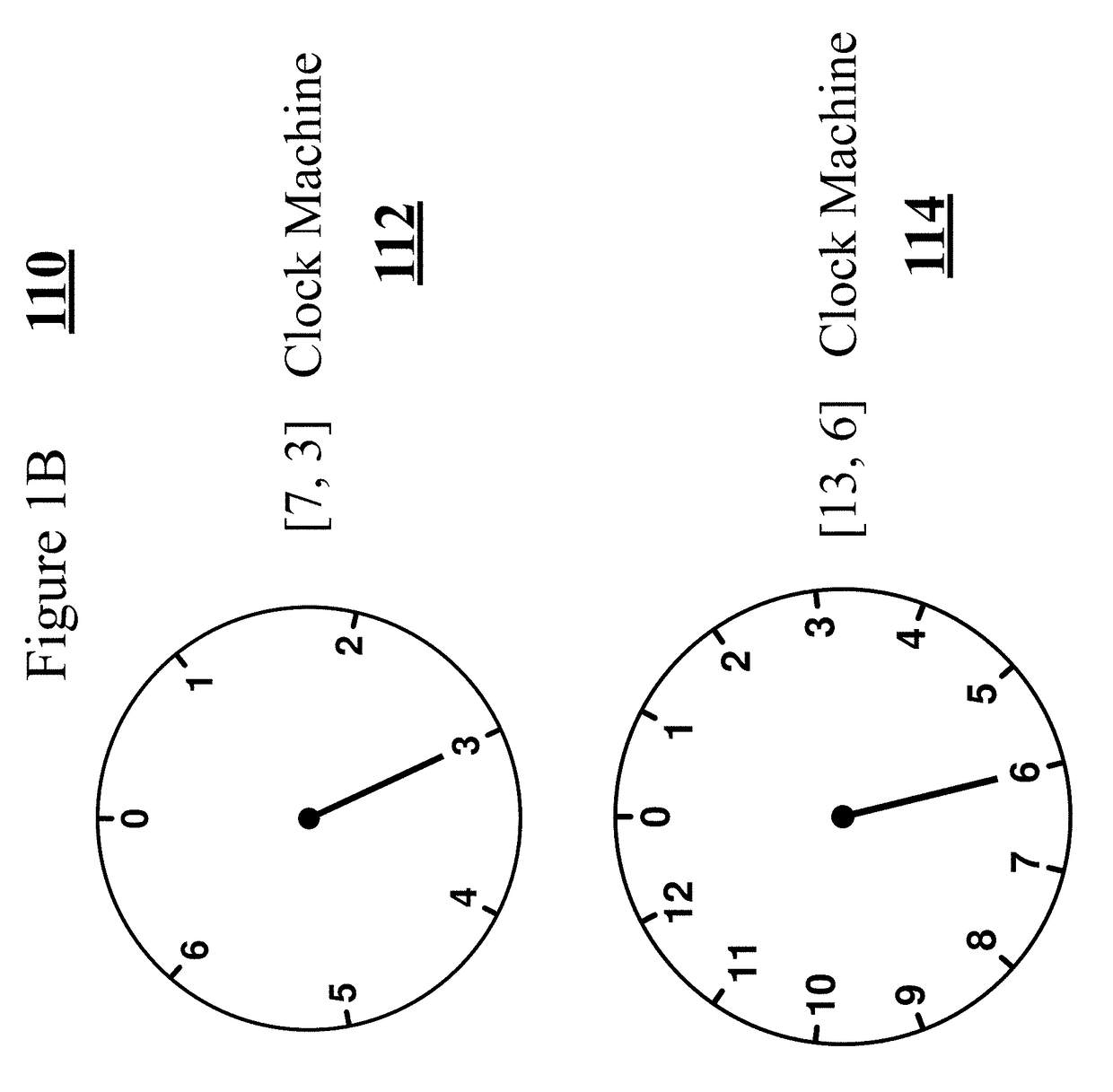
[0123]One can verify that the function 0:{0, 1}2×{0, 1}2→{0, 1} can be computed with the prime clock sum [2, 0]⊕[7, 3]⊕[7, 4]⊕[7, 5]⊕[11, 10], according to machine procedure 2. Similarly, the Boolean function 1 can be computed with the prime clock sum [2, 0]⊕[2, 1]⊕[3, 0]⊕[5, 2]⊕[11, 0]⊕[11, 1], according to machine procedure 2. The Boolean function 2 can be computed with the prime clock sum [5, 0]⊕[7, 0]⊕[7, 2]⊕[11, 4]. Lastly, the function 3 can be computed with the prime clock sum [2, 1]⊕[5, 0]⊕[11,1]⊕[11,6].

[0124]As described in machine specifications 1, 2, 3 and 5 and as shown ...


PUM


Abstract

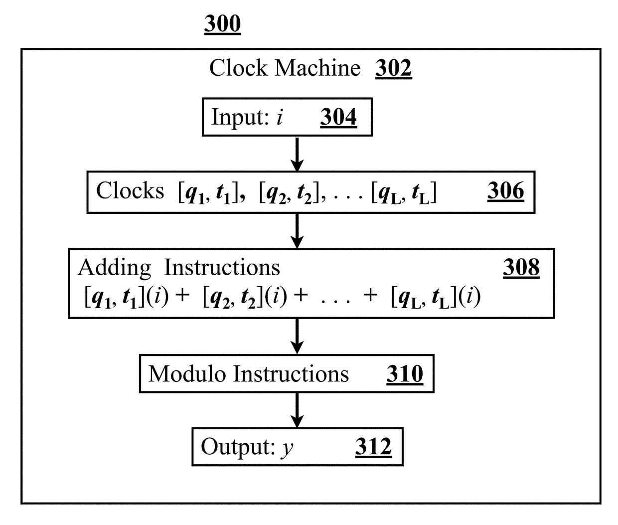
A new computational machine is invented, called a clock machine, that is a novel alternative to computing machines (digital computers) based on logic gates. In an embodiment, computation is performed with one or more clock machines that use time. In an embodiment, a cryptographic cipher is implemented with random clock machines, constructed from a non-deterministic process, wherein the compiled set of instructions (i.e., the implementation of the cryptographic procedure) is distinct on each device or chip that executes the cryptographic cipher. In an embodiment, by using a different set of clock machines to execute two different instances of the same cryptographic procedure, each execution of a procedure looks different to malware that may try to infect and subvert the cryptographic procedure. This cryptographic process also makes timing attacks more challenging. In an embodiment, a detailed implementation of the Midori cipher with random clock machines is described.

Description

RELATED APPLICATIONS[0001]This application claims priority benefit of U.S. Provisional Patent Application Ser. No. 62 / 357,191, entitled Prime Clock Computers, filed Jun. 30, 2016, which is incorporated herein by reference.BACKGROUNDField of Invention[0002]This invention broadly relates to computing machines and computers. This invention also demonstrates embodiments of this new computer that compute cryptographic machines and hence protect the privacy of information and also protect the execution of the computation.Prior Art[0003]The subject matter discussed in the background section should not be assumed to be prior art merely as a result of its mention in the background section. Similarly, a problem mentioned in the background section or associated with the subject matter of the background section should not be assumed to have been previously recognized in the prior art. The subject matter in the background section merely represents different approaches, which in and of themselves...

Claims


Application Information

Patent Timeline
Patent Type & Authority Applications(United States)
IPC IPC(8): H04L9/06G06F1/06
CPCG06F1/06H04L9/0618G06F21/725H04L9/0631H04L9/0643H04L9/005
Inventor FISKE, MICHAEL STEPHEN
Owner AEMEA
Learn More