
Thermal management device for heat generating power electronics incorporating high thermal conductivity pyrolytic graphite and cooling tubes

Active Publication Date: 2018-01-11
CPS TECH
View PDF10 Cites 1 Cited by
  • Summary
  • Abstract
  • Description
  • Claims
  • Application Information

AI Technical Summary

Benefits of technology

The patent is about a new thermal management system for heat generating devices. The system uses a composite structure made of high thermal conductivity pyrolytic graphite and a metal matrix composite. This composite structure helps to transfer heat from the device to a cooling stream more efficiently. The design also minimizes the thermal path and reduces the thermal resistance between materials, making it the best thermal dissipation performance. The system can include other structures, like dielectric substrates, to achieve even better thermal dissipation performance. Overall, this new system helps to manage heat better, leading to improved performance and reliability of heat generating devices.

Problems solved by technology

While the heat generated by the device is due to many factors, it generally relates to the fact that the device efficiency is always less than 100%, and the efficiency loss typically becomes heat.
Unfortunately, device performance tends to erode with increased temperatures and at certain temperature thresholds the device is destroyed.
Although a relatively good thermal contact is accomplished, the thermal interface material has certain thermal resistance, which is disadvantageous to heat exchange between the heat sink and the heated surface.

Method used


Image

  • Thermal management device for heat generating power electronics incorporating high thermal conductivity pyrolytic graphite and cooling tubes
  • Thermal management device for heat generating power electronics incorporating high thermal conductivity pyrolytic graphite and cooling tubes
  • Thermal management device for heat generating power electronics incorporating high thermal conductivity pyrolytic graphite and cooling tubes

Examples


Embodiment Construction

[0024]Various embodiments of the present disclosure will be described herein with reference to the accompanying drawings. The invention relates generally to the cooling of high power electronics that require a high heat dissipation into a material that has a controlled thermal expansion coefficient, the material being compatible with the devices to mitigate thermal cycling induced stresses that can lead to failure.

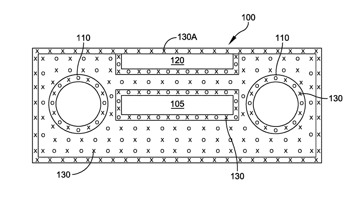
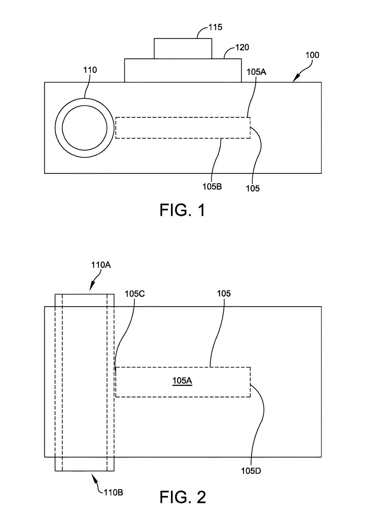
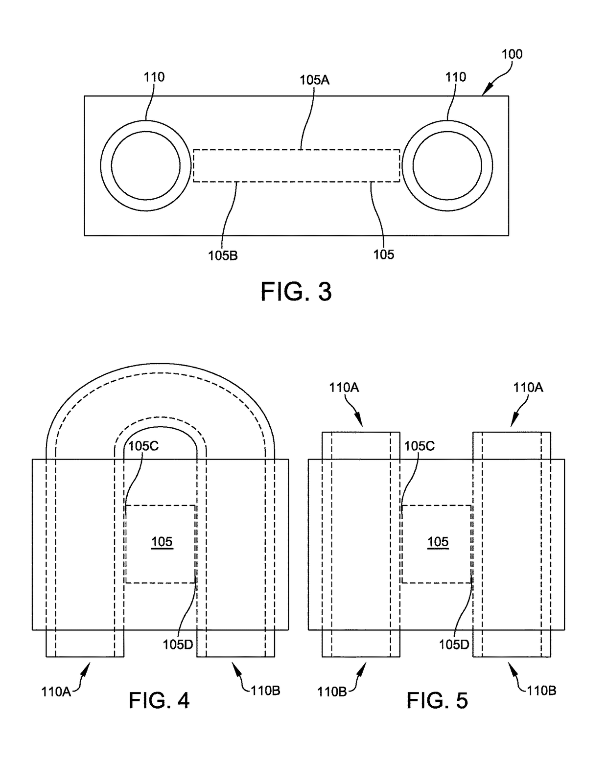
[0025]Referring to FIGS. 1 and 2, a cross-section of a cooling device of the present invention is illustrated. In its most general embodiment it includes an AlSiC (Aluminum Silicon Carbide) base 100 integrating a HTC-PG (Pyrolytic Graphite) material 105 for high lateral heat spreading within the AlSiC material. The in-plane thermal conductivity value of HTC-PG is 1300 W / mK. HTC-PG 105 is preferably a rectangular sheet having a top 105A, bottom 105B, left 105C, right 105D, front 105E and rear 105F surfaces.

[0026]In one embodiment, a heat generating electronic device 115 is ...


PUM


Abstract

The present invention is a system for cooling high power, heat generating devices. The system includes a metal matrix composite (AlSiC) having a coefficient of thermal expansion substantially equal to that of the heat generating device. The metal matrix composite (MMC) includes interior cooling channels and at least one Pyrolytic Graphite insert laterally positioned against the cooling channels. The heat generating device is placed on the metal matrix composite top surface in a substantially parallel relationship with the Pyrolytic Graphite insert surface area for maximum heat transfer efficiency.

Description

CROSS-REFERENCE TO RELATED APPLICATIONS[0001]The present application is related to, claims the earliest available effective filing date(s) from (e.g., claims earliest available priority dates for other than provisional patent applications; claims benefits under 35 USC §119(e) for provisional patent applications), and incorporates by reference in its entirety all subject matter of the following listed application(s) (the “Related Applications”) to the extent such subject matter is not inconsistent herewith; the present application also claims the earliest available effective filing date(s) from, and also incorporates by reference in its entirety all subject matter of any and all parent, grandparent, great-grandparent, etc. applications of the Related Application(s) to the extent such subject matter is not inconsistent herewith:[0002]U.S. provisional patent application 62 / 493,555 entitled “THERMAL RESISTANCE ALSIC POWER MODULE INTEGRATING HIGH THERMAL CONDUCTIVITY PYROLYTIC GRAPHITE A...

Claims


Application Information

Patent Timeline
IPC IPC(8): H05K7/20F28F21/08F28F21/02H01L23/473F28D15/00
CPCH05K7/20927F28F21/02H01L23/473F28D15/00F28F21/081
Inventor OCCHIONERO, MARK
Owner CPS TECH
Learn More