System for radiopharmaceutical production
a radiopharmaceutical and system technology, applied in the direction of chemical/physical processes, drug compositions, nuclear engineering, etc., can solve the problems of time-consuming processes, complex automation, and inability to target specific patients with specific conditions
- Summary
- Abstract
- Description
- Claims
- Application Information
AI Technical Summary
Benefits of technology
Problems solved by technology
Method used
Image

Examples
example 1
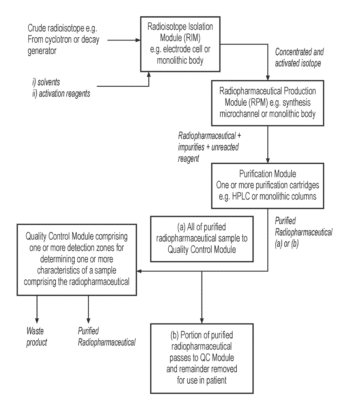
Radioisotope Isolation Module Comprising an Electrode Cell
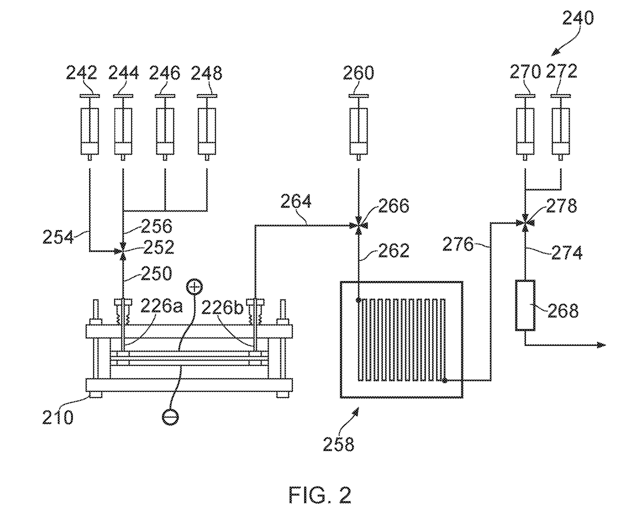
[0236]Microfluidic RIM cells were fabricated by clamping together two glass plates, a pair of electrodes (including a platinum counter electrode) and a silicon spacer comprising a channel. Details of the cells are provided in Table 1.
[0237]The cells were tested with a low volume of 18O-water comprising 18F from an ABT cyclotron. Trapping and release efficiencies were probed at different voltages with variation of the flow rate. The results are shown in Tables 2 and 3. Efficiencies of up to 99% in trapping (Table 2) and up to 98% in release (Table 3) were observed.
TABLE 1CelldesignWorking electrodeCell volume (μL)1Graphite (15x4 mm)302Carbon disk (10 mm diameter)323Carbon disk (10 mm diameter)164Carbon 8x3x0.25 mm6
TABLE 2Trapping conditionsCellVolume 18O-Flow rateTrappingdesignwater (mL)(mL / min)Voltage (V)efficiency %10.20.2209920.30.2209930.30.215-209840.30.214-2096-99
TABLE 3Release conditionsReleaseCellVolumeFlow rateVoltage...
example 2
Production
[0260]A mould is designed using SolidWorks software which was also used to program the CNC machine. The CNC machine was then used to mill the mould out of PTFE.
[0261]0.282 g polyethylene oxide (PEO) was added to a 50 mL falcon tube and cooled with ice. 2.54 mL nitric acid (1N) was added and the mixture stirred. 0.29 mL water was then added and the mixture left for 1 hour maintaining cooling. After 1 hour, 2.26 mL tetraethyl orthosilicate (TEOS) was added and stirring and cooling continued.
[0262]The PTFE mould in two halves was put together in a holder and heated at 40° C. for 1 hour, after which the holder was tightened to ensure no leakage. After 1 hour of stirring, the PEO / TEOS mixture was injected into the mould ensuring the mould was filled and all air escaped. A clamp with a parafilm layer was placed against the mould inlets and tightened to seal the mould and the whole apparatus heated to 40° C. for 72 hours. After this time, the clamp was removed and the two halves ...
example 3
of Silicon Nitride, Silicon Imido Nitride and Silicon Silicon Imide Monolithic Bodies
[0269]Details for the preparation of certain silicon nitride materials can be found in WO 2006 / 046012 which describes a sol-gel procedure for the preparation of materials based on silicon nitride and silicon oxynitride. Monolithic bodies comprising silicon imido nitride, silicon imide and / or silicon nitride and processes for their preparation are disclosed in WO 2013 / 054129. Monolithic bodies comprising silicon imido nitride, silicon imide and / or silicon nitride as described herein can be prepared according to the preparation procedures described in WO 2006 / 046012 and WO 2013 / 054129.
[0270]Silicon diimide mesoporous gel is optionally partially pyrolysed to form a silicon imido nitride, or completely pyrolysed to form a silicon nitride ceramic material.
PUM
| Property | Measurement | Unit |
|---|---|---|
| distance | aaaaa | aaaaa |
| flow rate | aaaaa | aaaaa |
| total volume capacity | aaaaa | aaaaa |
Abstract
Description
Claims
Application Information
 - R&D
- Intellectual Property
- Life Sciences
- Materials
- Tech Scout
- Unparalleled Data Quality
- Higher Quality Content
- 60% Fewer Hallucinations
Browse by: Latest US Patents, China's latest patents, Technical Efficacy Thesaurus, Application Domain, Technology Topic, Popular Technical Reports.
© 2025 PatSnap. All rights reserved.Legal|Privacy policy|Modern Slavery Act Transparency Statement|Sitemap|About US| Contact US: help@patsnap.com