
Method and plant for denitrifying bypass gases in a multi-stage system of mixing chambers in a plant for producing cement clinker

Active Publication Date: 2018-02-08
KHD HUMBOLDT WEDAG GMBH
View PDF1 Cites 2 Cited by
  • Summary
  • Abstract
  • Description
  • Claims
  • Application Information

AI Technical Summary

Benefits of technology

The invention is a system for purifying the exhaust gas that is produced by a vehicle's engine. The system includes two mixing chambers, with the second chamber designed to cool the exhaust gas to a specific temperature range. This temperature range prevents the formation of harmful pollutants such as dioxins and furans. The cooling medium that is injected into the chambers can be water, air, or a combination of both. The cooling can occur in stages, with water or air being injected at different points in the chambers to achieve maximum mixing and uniform cooling. The system can also reduce the sulfur dioxide content of the exhaust gas and act as a sorbent for pollutant purification. Overall, the system helps to purify the exhaust gas and reduce harmful emissions.

Problems solved by technology

A problem affecting the operation of cement clinker production is the formation and / or release of a series of pollutants.
A further problem is that the raw materials for cement clinker production, and also the fuels employed, especially secondary fuels, contain by-constituents (alkali metal compounds, chlorine, sulfur compounds, heavy metals, etc.) which not only may be detrimental to the quality of the combustion process and / or of the cement clinker, but may also form deleterious substance circuits within the plant for cement clinker production.
Further to the disadvantages of such substance circuits for the cement clinker and the combustion process, rapid cooling and condensation of these compounds give rise, through solidification, to caking on the walls of the cooler sections of the circuit, which may cause the plant to become blocked over time.
In the case of the desired denitrification of bypass exhaust gas, however, denitrification by the SNCR process proves to be problematic, since the temperatures of the bypass exhaust gas drawn off are too high and, in addition, compliance with the residence time in the reaction space imposes exacting requirements on the operating regime.
For effective denitrification, however, this operation is not suitable.
Capital costs and operating costs for the catalyst and / or catalytic filter required in the case of SCR, however, are comparatively high.

Method used


Image

  • Method and plant for denitrifying bypass gases in a multi-stage system of mixing chambers in a plant for producing cement clinker
  • Method and plant for denitrifying bypass gases in a multi-stage system of mixing chambers in a plant for producing cement clinker

Examples


Embodiment Construction

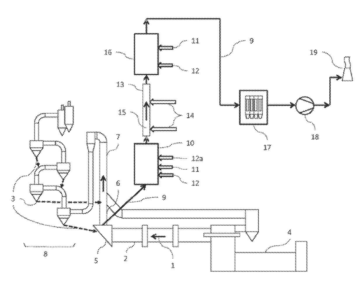
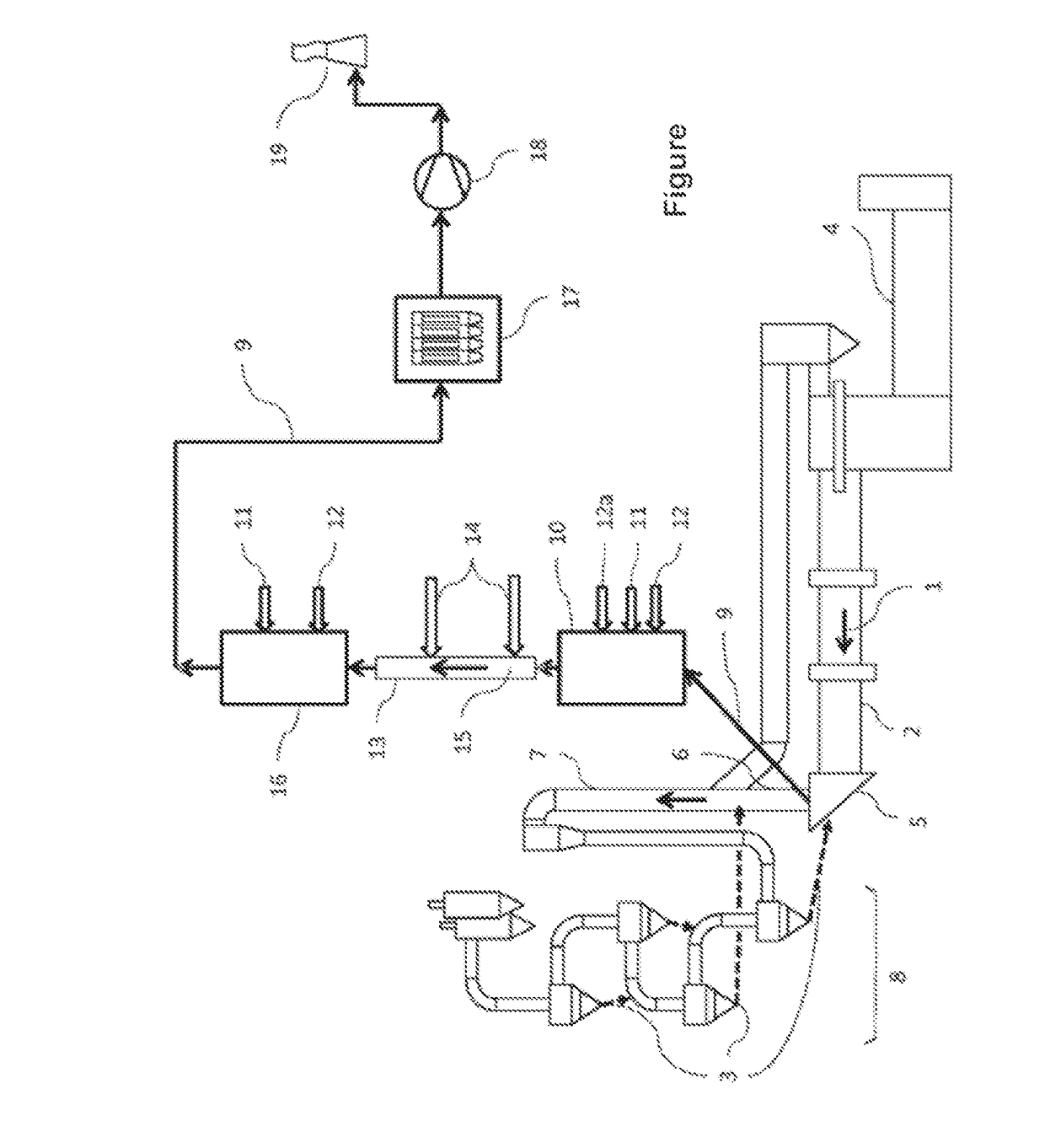
[0021]In the FIGURE it is evident schematically that flue gas 1 flows into the rotary kiln inlet chamber 5 from a rotary kiln 2, in which raw meal 3 is sintered to form cement clinker which is then cooled in a clinker cooler 4. Following this in the direction of gas flow, in the working example depicted, are a kiln riser duct 6 and a calciner 7 for the deacidification of the raw meal 3. A fraction of the flue gas 1 (kiln exhaust gas) flows through kiln riser duct 6 and calciner 7 into the heat exchanger 8 (presently a multistage cyclone heat exchanger), which serves for the preheating of the raw meal 3 for cement production.

[0022]In accordance with the invention, a part of the flue gas stream 1 emerging from the rotary kiln 2 is drawn off as bypass exhaust gas 9 in the region of the rotary kiln inlet chamber 5, i.e., from the rotary kiln inlet chamber 5 or from the kiln riser duct 6. The bypass exhaust gas 9, which initially on emergence from the rotary kiln 2 has temperatures typic...


PUM

PropertyMeasurementUnit
Temperatureaaaaaaaaaa

Abstract

A method and a corresponding plant for denitrifying bypass exhaust gases in a cement clinker production plant. Raw meal is sintered in a rotary kiln and deacidified in a calciner. A rotary kiln inlet chamber is connected to the calciner directly or by a riser duct. Bypass exhaust gas is drawn off near the inlet chamber. This exhaust gas is guided into a first mixing chamber, in which the exhaust gas is cooled to between 800 and 950 degrees C., then the exhaust gas is guided through a reaction pipeline segment, wherein the dwell time is between 0.5 and 3 seconds and ammonia, aqueous ammonia solution, or ammonia-releasing substances are injected for denitrification. Then the exhaust gas is guided into a second mixing chamber, in which the exhaust gas is cooled to between 150 250 degrees C. Then the exhaust gas is guided to a filter for dust removal.

Description

CROSS-REFERENCES TO RELATED APPLICATIONS[0001]This application claims the benefit of the German patent application No. 10 2015 002 688.7 filed on Mar. 4, 2015, the entire disclosures of which are incorporated herein by way of reference.BACKGROUND OF THE INVENTION[0002]The invention relates to a method for the denitrification of bypass exhaust gases in a plant for producing cement clinker, wherein the plant has a rotary kiln for the sintering of raw meal to cement clinker and has a calciner for the deacidification of the raw meal, downstream of the rotary kiln in the kiln exhaust gas flow direction, the rotary kiln has a rotary kiln inlet chamber which is connected directly or via a kiln riser duct to the calciner, and the bypass exhaust gas is drawn off in the region of the rotary kiln inlet chamber. The invention further relates to a corresponding plant for the denitrification of bypass exhaust gases in the production of cement clinker, comprising a rotary kiln for the sintering of...

Claims


Application Information

Patent Timeline
IPC IPC(8): F27B7/20B01D53/56C04B7/36F27D17/00C04B7/44
CPCF27B7/20F27D17/008F27D17/004C04B7/44C04B7/364B01D53/56F27B2007/2091C04B7/43C04B7/60
Inventor SCHUERMANN, HEIKONASSENSTEIN, FLORIANHAND, ANDREASGUSSMANN, ROLF
Owner KHD HUMBOLDT WEDAG GMBH
Learn More