
Start-up procedure for rapid attainment of optimal steady-state performance in membrane separation

a technology of membrane separation and steady-state performance, applied in the field of liquid mixture separation systems and methods, can solve the problems of large steam consumption, low separation efficiency per pass, and limit the economic viability of distillation in certain situations

Pending Publication Date: 2022-11-10
SABIC GLOBAL TECH BV
View PDF0 Cites 0 Cited by
  • Summary
  • Abstract
  • Description
  • Claims
  • Application Information

AI Technical Summary

Benefits of technology

The present invention provides a method for separating water and organic compounds using a startup step and membrane separation under optimal conditions. The method allows for quicker attainment of steady state compared to conventional methods and can lead to increased membrane lifetime, increased flux per unit area, and increased permeate purity. The method can also be adjusted using machine learning and other algorithms, resulting in quick and accurate adjustment of the conditions and parameters for the method. Overall, the method solves some of the problems associated with conventional methods for separating water and organic liquid.

Problems solved by technology

However, several drawbacks, including high energy demand, large steam consumption, and low separation efficiency per pass, limit the economic viability of distillation in certain situations.
Separation of mixtures of water and organic compounds such as diols, alcohols, and polyols generally requires a large amount of energy.
Therefore, separation of such water-organic compound mixtures generally requires high capital expenditure and high operational costs.
Membrane based techniques, including reverse osmosis, nanofiltration, ultrafiltration and pervaporation, have been explored for liquid mixture separation applications, but the implementation of these technologies on commercial scales is still low due to factors including low separation factor, low fluxes, lack of consistent performance, limited lifetime of membranes and loss of product to lower permeate purities.
The flux and selectivity of the best membranes available are limited.
Therefore, a large membrane area and / or operation in combination with another separation technique are required to separate compounds of liquid mixtures, which result in limited economic feasibility for membrane based processes.

Method used


Image

  • Start-up procedure for rapid attainment of optimal steady-state performance in membrane separation
  • Start-up procedure for rapid attainment of optimal steady-state performance in membrane separation

Examples


example 1

Pervaporation Experiment in a Pilot Scale System

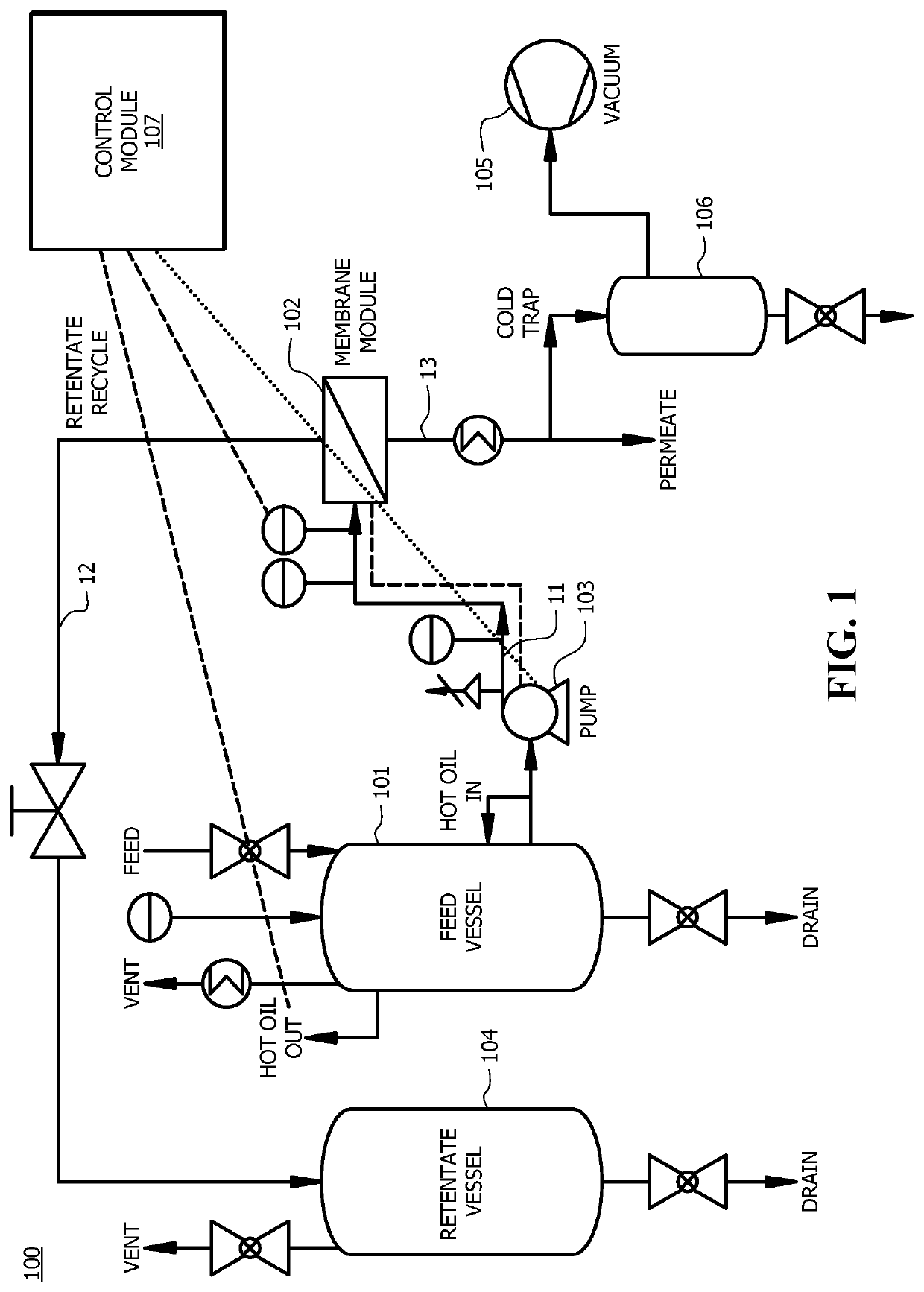
[0044]A liquid mixture of monoethylene glycol and water was separated using a Pervatech® membrane at a pilot plant. Each membrane module in the pilot plant included 10 membrane tubes. Each membrane tube had an outer diameter of 10.04 mm and inner diameter of 6.5 mm. The wall thickness for each membrane tube was 1.89 mm. The contacting area of each membrane tube was about 46.9 cm2. The feed concentration of monoethylene glycol was in a range of 2 to 80 wt. %. The flowrate was in a range of 100 to 1000 L / hr. The feed temperature was in a range of 90 to 140° C. The feed pressure was set in a range of 1-5 bar. The vacuum on the permeate was in a range 50 to 70 mbar. Cooling water used for recovering the permeate was at about 5° C. Simulations on the separation process were also performed in Aspen (versions 9 and 10), ACM-Aspen Custom Modeler. Statistical modeling was performed in GAMS and JMP.

[0045]The experimental results are shown in Tab...


PUM


Abstract

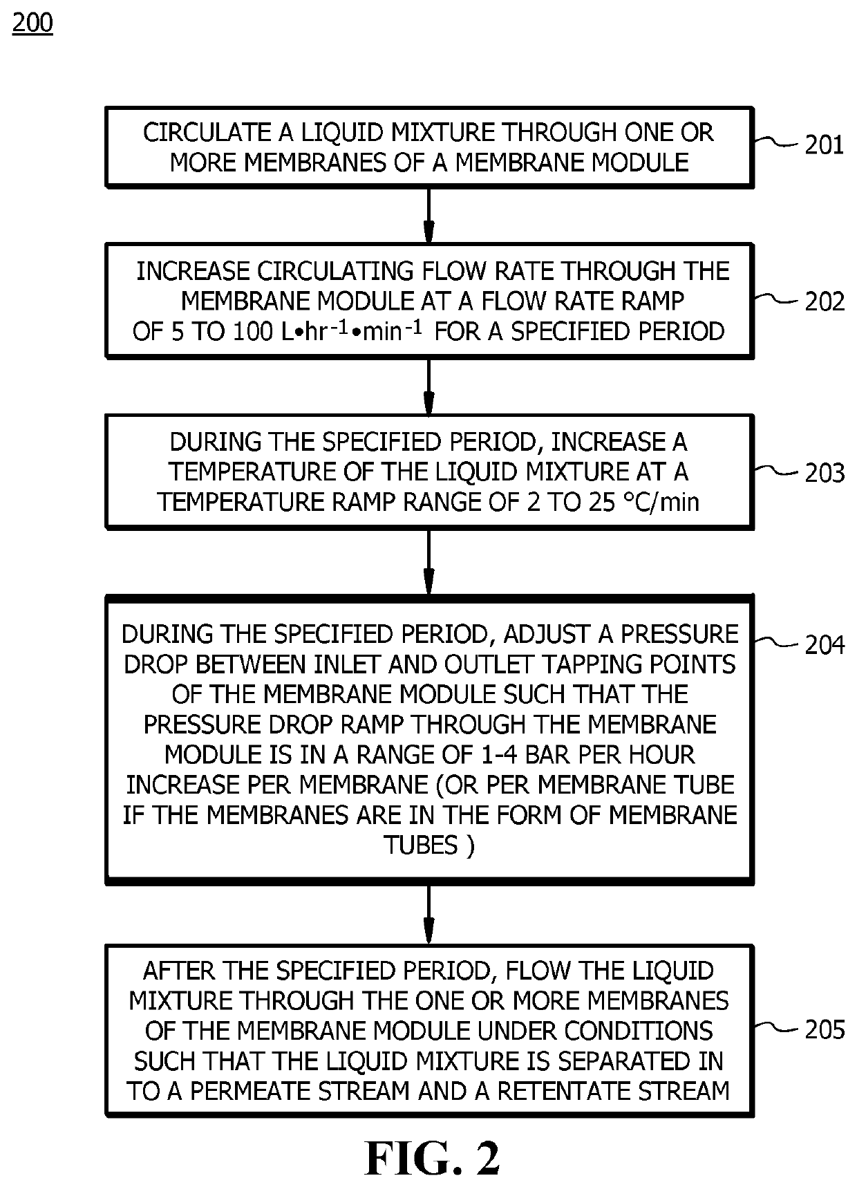
Systems and methods for separating a liquid mixture are disclosed. A membrane is first soaked by the liquid mixture via dynamic soaking to reach steady state. During the soaking process, the flow rate of the liquid mixture is increased at a flow rate ramp, the temperature is increased at a temperature ramp, and the pressure drop is increased at a pressure drop ramp. After the soaking process, the liquid mixture is separated by the membrane under optimized conditions to produce a permeate and a retentate.

Description

CROSS REFERENCE TO RELATED APPLICATIONS[0001]This application claims the benefit of priority of U.S. Provisional Patent Application No. 62 / 906,385, filed Sep. 26, 2019, which is hereby incorporated by reference in its entirety.FIELD OF INVENTION[0002]The present invention generally relates to systems and methods for liquid mixture separation. More specifically, the present invention relates to membrane based systems and methods for liquid mixture separation that includes a start-up procedure to quickly attain steady state.BACKGROUND OF THE INVENTION[0003]Separation of liquid mixtures is an important process in the chemical industry for purifying products and / or recovering unreacted materials. Conventionally, distillation has been the most widely used technique for separating liquid components. However, several drawbacks, including high energy demand, large steam consumption, and low separation efficiency per pass, limit the economic viability of distillation in certain situations.[0...

Claims


Application Information

Patent Timeline
IPC IPC(8): B01D61/36B01D63/06
CPCB01D61/362B01D63/068B01D2311/02B01D2311/22B01D2311/25B01D2315/10B01D2311/103B01D2311/14B01D2311/16B01D2313/70B01D17/02B01D63/06B01D2311/2523
Inventor SANKAR, ASHWIN RAVI
Owner SABIC GLOBAL TECH BV
Learn More