MEMS capacitive shear sensor system having an interface circuit

a capacitive shear sensor and interface circuit technology, applied in the direction of printed circuit non-printed electric components, instruments, semiconductor/solid-state device details, etc., can solve the problems of inability to use inability to real-time acquire and inability to achieve real-time acquisition of the wall shear stress field using the current research tools. , to achieve the effect of reducing the drag on the aerodynamic, extending the measuremen

Active Publication Date: 2018-02-08
UNIV OF FLORIDA RES FOUNDATION INC
View PDF17 Cites 4 Cited by
  • Summary
  • Abstract
  • Description
  • Claims
  • Application Information

AI Technical Summary

Benefits of technology

[0009]This non-intrusive MEMS enabled system is capable of directly measuring simultaneous directional AC and DC baseband shear stress values in real time with spatial and temporal accuracy, resolving significant flow components found inside turbulent boundary layers. It is capable of making a time resolved, vector measurement of wall shear stress in order to detect and likely flow predict separation. This measurement can be used in a feedback mechanism to enhance a system's ability to suppress and even prevent flow separation.
[0010]Beyond flow separation, this system uses direct time-resolved measurements of mean and dynamic wall shear stress to help clarify other complex flow fields, where traditional fluid measurement techniques used to estimate wall shear stress fail. The system's ability to make a wall shear stress measurement may also provide information about momentum transfer to the wall and overall flow state. Such information could help steer the design process to lower drag on aerodynamic (and hydrodynamic) surfaces.
[0011]The system's novel interface and support electronics incorporate a synchronous modulation/demodulation system employi

Problems solved by technology

Using the current set of research tools, time-resolved characterization of complex, three-dimensional, wall-bounded flow fields may be difficult.
However, real-time acquisition of the wall shear stress field is not available using the current set of research tools.
In particular, although a Micro-Electro-Mechanical Systems (MEMS) shear stress sensor enables the direct measurement of wall shear stress on an associated lifting body (such as a plane or a submarine in a fluid or gas), this MEMS sensor is only available for bench-top testing.
Measurement of wall shear stress, however, m

Method used


Image

  • MEMS capacitive shear sensor system having an interface circuit
  • MEMS capacitive shear sensor system having an interface circuit
  • MEMS capacitive shear sensor system having an interface circuit

Examples


Embodiment Construction

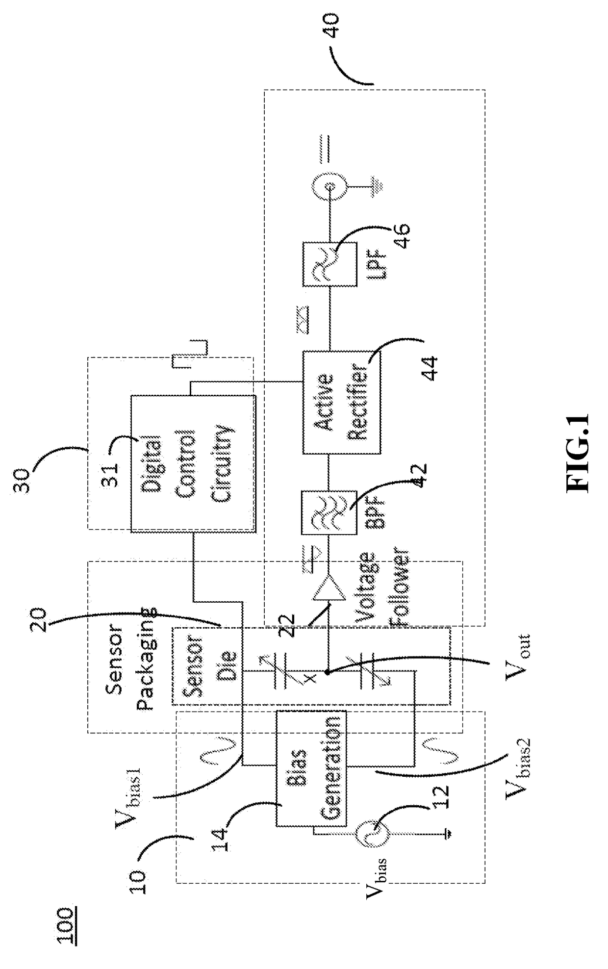
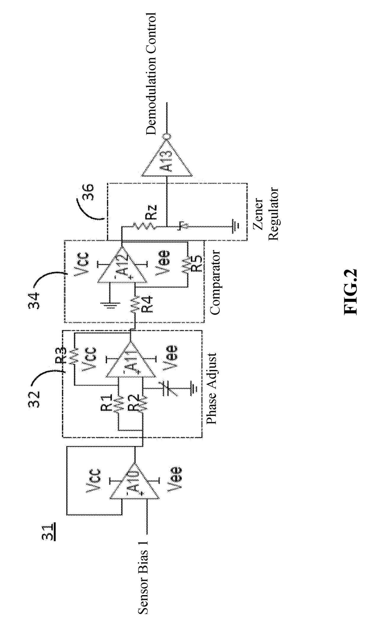
[0029]Sensor systems, having interface circuitry, and methods for a measuring the shear stress of an object without greatly impacting the overall performance of the sensor are disclosed herein. The shear stress sensor system may comprise a sensor for sensing wall shear stress at the surface of an object in a fluid and, thereby, in response generate a sensor output signal. The sensor system may include one of a variety of MEMS-based capacitive floating element shear stress sensors. Embodiments of the shear stress sensor system may further comprise an interface circuit having a modulation section for generating at least one bias signal for biasing the sensor and a demodulation section for demodulating the sensor output signal. An embodiment of the demodulation section may include a rectification unit for rectifying the sensor output signal. A demodulation control circuit may generate a demodulation control signal in response to at least one bias signal. The demodulation control circui...


PUM


Abstract

A sensor system comprising a Micro-Electro-Mechanical Systems (MEMS)-based capacitive floating element shear stress sensor, the associated packaging, and the interface circuitry required for operation as an instrumentation-grade sensing system is disclosed herein. One implementation of the interface circuitry is an analog synchronous modulation/demodulation scheme enabling time-resolved measurements of both mean and dynamic wall shear stress events, where a modulation section couples to the sensor for sensing wall shear stress at the surface of an object in a fluid and generates at least one bias signal from the sensor output signal. In response to the bias signal, a demodulation control circuit adjusts the phase of the bias signal and generates a demodulation control signal from the phase adjusted signal. Consequently, in response to the demodulation control signal, a demodulation section synchronizes the rectification of the sensor output signal, while the phase information is maintained.

Description

CROSS-REFERENCE TO A RELATED APPLICATION[0001]This application claims the priority benefit of U.S. Provisional Application Ser. No. 62 / 115,317, filed Feb. 12, 2015, which is incorporated herein by reference in its entirety.GOVERNMENT SUPPORT[0002]This invention was made with government support under grants awarded from The National Aeronautics and Space Administration (NASA) under grant numbers NNX11CG91P, NNX09AJ13H, and NNX07AB27A. The government has rights in the invention.BACKGROUND[0003]Using the current set of research tools, time-resolved characterization of complex, three-dimensional, wall-bounded flow fields may be difficult. One such wall-bounded flow field is the fluctuating wall shear stress field, which when acquired in real-time, may have the ability to significantly impact the characterization, design, and control of fluidic systems. However, real-time acquisition of the wall shear stress field is not available using the current set of research tools. In particular, a...

Claims


Application Information

Patent Timeline
IPC IPC(8): G01L1/14G01N11/00H05K1/18B81B7/00H01L23/00
CPCG01L1/144B81B7/007B81B7/0064H01L24/48H05K1/183G01N11/00B81B2207/012B81B2207/096H01L2224/48227H01L2924/1461H01L2924/1433H01L2924/3025H05K2201/10151G01L1/146G01N11/02H01L2224/48465H01L2924/00014H01L2924/00H01L2224/45099
Inventor BARNARD, CASEY A.MELOY, JESSICA C.SHEPLAK, MARK
Owner UNIV OF FLORIDA RES FOUNDATION INC
Why Eureka
Try Eureka