A Weld

Pending Publication Date: 2018-02-15
SPI LASERS UK
View PDF5 Cites 17 Cited by
  • Summary
  • Abstract
  • Description
  • Claims
  • Application Information

AI Technical Summary

Benefits of technology

[0042]At least one of the first, second and the third signals may b

Problems solved by technology

This is because the surface of the bright metals is highly reflective with poor absorbance.
It is consequently very difficult to control.
The challenge is increased when welding thin and low mass work pieces.
High power densities are often detrimental, leading to over penetration of the laser beam, which results in unreliable joints.
Thermal heat sinking of the absorbed energy into the regions surrounding the weld can then cause overheating of the work piece, resulting in weak or absent welds.
The laser joining of bright metals with such lasers produces welds that are repeatable and consistent but at the cost of efficiency, complexity, and costs associated with frequency doubling.
These systems are complex and expensive.
Large intermetallic regions are prone to fracture from stresses acting on the joint, and the fracture propagates through the entire joint until f

Method used


Image

  • A Weld
  • A Weld
  • A Weld

Examples


Example

Example 1

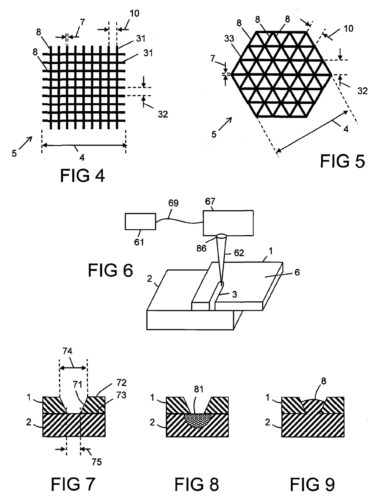
[0202]FIG. 15 shows an artistic impression of a cross-section through a weld 310 formed between copper having a thickness 143 of 100 μm and aluminium having a thickness 144 of 400 μm. The weld 310 was in the shape of the spiral, shown with reference to FIG. 2, with a first separation 10 of 50 μm between the spiral arms 9, and a diameter 4 of 1 mm. The width 74 of the hole 71 was approximately 5 μm to 20 μm. The weld 310 was formed using multiple pulses 161 from the laser 61, which pulses 161 overlayed each other on the first material 1 by approximately 95% to 98% in area. The laser 61 has cut the first material 1, which is copper, and the second material 2 (aluminium) has flowed into the hole 71. At least some of the first material 1 has been injected into the second material 2, as evidenced by the zones 121 that comprise the first material 1. The zones 121 extend to approximately 300 μm to 400 μm into the second material 2. Voids 122 are also present. A heat affected zone ...

Example

Example 2

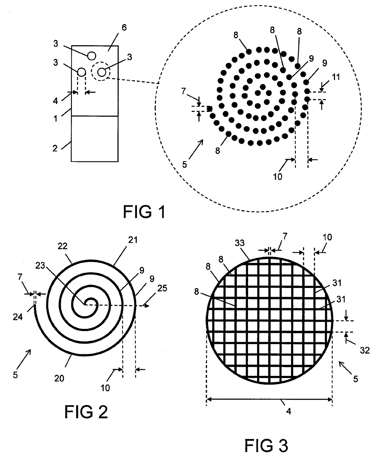
[0206]FIG. 34 shows an artistic impression of a cross section of a weld 340 between a first material 1 copper and a second material 2 brass. The weld 340 was also formed in a similar spiral to the weld 310 shown with reference to FIG. 13. It is surprising that the brass has flowed into the copper material to form the weld 340 with very little intermetallic mixing. The weld 340 is substantially inhomogeneous. The copper and the brass have flowed, but have not mixed together to form new homogeneous material phases. The material phases of the copper and the brass are largely unmixed, with the copper and the brass being in their original material phases. This is particularly surprising given that brass is an alloy of copper and zinc. There are zones 121 of the first material 1 contained within the second material 2. There are also voids 122. The resulting joint formed by the weld 340 has excellent shear strength.

Example

Examples 3 to 10

[0207]The laser 61 used in Examples 3 to 10 was a nanosecond ytterbium-doped fibre laser, model SPI G4 70 W HS-H manufactured by SPI Lasers UK Ltd of Southampton, England. The laser is substantially similar to the laser used in Examples 1 and 2, though with a poorer beam quality 146, which was increased from approximately M2=1.6 to approximately M2=3. The spot size 174 was approximately 80 μm, which is approximately twice as large as obtained with the higher brightness laser used in Examples 1 and 2. Similar waveforms are provided with the laser as were described with reference to Table 1 and FIGS. 25 and 36.

[0208]Table 2 shows details of the welds 3 in Examples 3 to 10. The first metal listed in each example was the first material 1, and the second metal listed was the second material 2.

[0209]The welding pattern 5 was the rectangular hatching of FIG. 3. The first separation 10 and the third separation 32 were both equal to each other, and were varied between 0.2 mm ...


PUM

PropertyMeasurementUnit
Lengthaaaaaaaaaa
Lengthaaaaaaaaaa
Lengthaaaaaaaaaa

Abstract

A weld (3) between a first material (1) and a second material (2), the first material (1) being a first metallic material, and the second material (2) being a second metallic material, the weld (3) has a width (4) between 0.5 mm and 7 mm, the weld (3) comprises at least one microweld (8), the microweld (8) forms a welding pattern (5) defined parallel to a surface (6) of the first material (1), and the microweld (8) has a characteristic feature size (7) of between 20 μm and 400 um.

Description

FIELD OF INVENTION[0001]This invention relates to a weld. The weld may join one or more reflective materials. The weld may have a low ohmic resistance, a high shear strength, and a high peel strength. This invention also relates to an article comprising the weld and a method for laser welding.BACKGROUND TO THE INVENTION[0002]The joining of bright metals such as gold, copper, aluminium, platinum and silver by laser welding in the near infrared spectrum (800 nm to 2500 nm) presents a challenge. This is because the surface of the bright metals is highly reflective with poor absorbance. To overcome the surface reflectivity and initiate coupling of the laser's energy into the metal surface, it is necessary to use laser beams with high power densities.[0003]The function of the laser beam on a bright material approximates a discreet function with a very narrow operating window from beam hold-off (reflection) and absorption. At first the surface reflects substantially all of the laser light...

Claims


Application Information

Patent Timeline
IPC IPC(8): F16B5/08B23K26/06B23K26/0622B23K26/323B23K26/10B23K26/22B23K26/244B23K26/00B23K26/082
CPCF16B5/08B23K26/0006B23K26/0084B23K26/0608B23K26/0622B23K26/082B23K26/10B23K26/22B23K26/244B23K26/323B23K26/24B23K26/21B23K26/08B23K26/32B23K26/355
Inventor CAPOSTAGNO, DANIEL ANTHONYGABZDYL, JACEK TADEUSZVARNHAM, MALCOLM PAULHARRISON, PAUL MARTINNORMAN, STEPHEN ROYROSOWSKI, ADAM PIOTRMURPHY, TARA
Owner SPI LASERS UK
Why Eureka
Try Eureka