Coherence range imaging using common path interference

a coherence range and path interference technology, applied in the field of optical coherence tomography, can solve the problems of difficult to maximize snr, inefficient coupling of reference light back to a fiber, and more light loss, and achieve efficient geometric coupling of reference light or reference reflection, and control and efficient reference signal or reference reflection

Active Publication Date: 2018-02-15
CANON USA
View PDF11 Cites 13 Cited by
  • Summary
  • Abstract
  • Description
  • Claims
  • Application Information

AI Technical Summary

Benefits of technology

[0010]Accordingly, it is a broad object of the present disclosure to provide OCT devices, systems, methods and storage mediums using a common path interference optical system, such as a common path interferometer (e.g., SD-OCT, SS-OCT, etc.), with a controlled and efficient reference signal or reference reflection, and with efficient geometric coupling of said reflection.

Problems solved by technology

However, if the reference coupling efficiency is low or if it is not possible to properly adjust to a desired reference signal power level, then it may be difficult to maximize SNR.
However, such use of certain materials can lead to a discreet set of values only because of the possibility of having a difference(s) between an index of refraction for selected materials.
As such, when coupling efficiency is less than ideal in devices using an adjustment section, even more light is lost.
However, reference light has not been efficiently coupled back to a fiber, and, therefore, the reference light cannot properly be used to image luminal or other hollow structures.
The difficulty in imaging when the reference signal is too low or sometimes too high applies generally to all sample types and structures.
When the signal is too high, other sources of noise start to overtake the SNR.
The aforementioned structures can lead to one or more of path length mismatches, dispersion mismatches and / or polarization mismatches while making one or more measurements.

Method used


Image

  • Coherence range imaging using common path interference
  • Coherence range imaging using common path interference
  • Coherence range imaging using common path interference

Examples


Embodiment Construction

[0048]One or more devices, optical systems, methods and storage mediums for performing coherence range imaging using a common path OCT technique are disclosed herein. In accordance with at least one aspect of the present disclosure, one or more devices, optical systems, methods and storage mediums discussed herein use a common path OCT technique with a controlled reference signal and efficient geometric coupling.

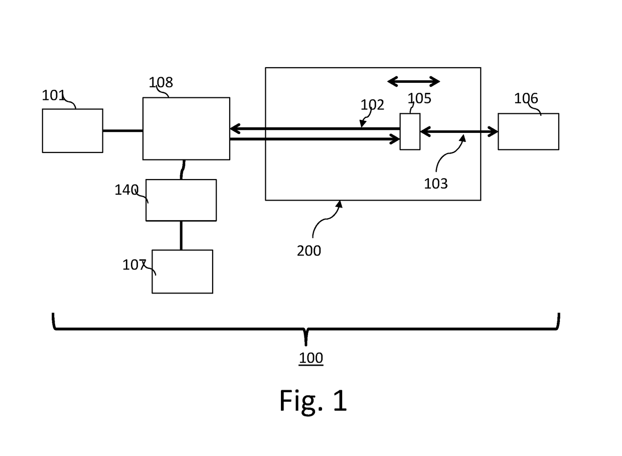
[0049]Turning now to the details of the figures, FIG. 1 shows an embodiment of an interference optical system 100 (as referred to herein as “system 100” or “the system 100”) which operates to utilize a common path OCT technique with optical probe applications in accordance with one or more aspects of the present disclosure. The system 100 comprises a light source 101, a reference arm 102, a sample arm 103, a deflected section 108 (e.g., a collimating lens or fiber; the deflected section 108 is also referred to herein as a deflecting section 105), a reference mirror (also ref...


PUM


Abstract

One or more devices, systems, methods and storage mediums for performing common path optical coherence tomography (OCT) with a controlled reference signal and efficient geometric coupling are provided. Examples of such applications include imaging, evaluating and diagnosing biological objects, such as, but not limited to, for Gastro-intestinal, cardio and/or ophthalmic applications, and being obtained via one or more optical instruments, such as, but not limited to, optical probes (e.g., common path probes), common path catheters, common path capsules and common path needles (e.g., a biopsy needle). Preferably, the OCT devices, systems methods and storage mediums include or involve a reference reflection or a reference plane that is at least one of: (i) disposed in the collimation field or path; and (ii) is perpendicular (or normal) or substantially perpendicular (or substantially normal) to light propagation. One or more embodiments may include beam shaping optics to properly image luminal or other hollow structures or objects.

Description

CROSS-REFERENCE TO RELATED APPLICATION(S)[0001]This application claims priority to U.S. Provisional Application Ser. No. 62 / 374,324 field Aug. 12, 2016, the content of which is incorporated herein by reference in its entirety.FIELD OF THE INVENTION[0002]The present disclosure relates generally to the field of optical imaging and more particularly to optical coherence tomography (OCT) devices, systems, methods and storage mediums using a common path interference optical system, such as a common path interferometer, with a controlled reference signal and efficient geometric coupling. Examples of such applications include imaging, evaluating and diagnosing biological objects, such as, but not limited to, for gastro-intestinal, cardio and / or ophthalmic applications, and being obtained via one or more optical instruments, such as, but not limited to, one or more common path optical probes, one or more common path catheters, one or more common path endoscopes, one or more common path caps...

Claims


Application Information

Patent Timeline
Patent Type & Authority Applications(United States)
IPC IPC(8): G01B9/02
CPCG01B9/02015G01B9/02091G01B9/02057A61B5/0066G01B9/0205
Inventor ELMAANAOUI, BADR
Owner CANON USA
Why Eureka
Try Eureka