Optical rare-earth doped fiber long period grating based ionizing radiation dose sensor device

a technology of ionizing radiation dose and optical rare earth doped fiber, which is applied in the field of fiber optic sensors, can solve the problems of critical limitations on their usage, limiting its application at site, and not being viable in commer

a technology of ionizing radiation dose and optical rare earth doped fiber, which is applied in the field of fiber optic sensors, can solve the problems of critical limitations on their usage, limiting its application at site, and not being viable in commer

US20180045835A1Inactive Publication Date: 2018-02-15SEC DEPT OF ATOMIC ENERY GOVERNMENT OF INDIA

Image

  • Optical rare-earth doped fiber long period grating based ionizing radiation dose sensor device
  • Optical rare-earth doped fiber long period grating based ionizing radiation dose sensor device
  • Optical rare-earth doped fiber long period grating based ionizing radiation dose sensor device

Examples


Embodiment Construction

[0029]Long period fiber gratings (LPFGs) that satisfy the phase matching condition between fundamental core mode and a set of forward propagating cladding modes in an optical fiber are of interest for making devices in the field of optical fiber sensors. As a precursor to practical device design, ease of fabrication, low cost, high sensitivity and reduced cross sensitivity are important considerations.

[0030]It is well known that resonance wavelength λ of a LPFG with period A is determined by phase matching condition.

λ=[ncoreeff−nclad,neff]Λ  (1)

[0031]where ncoreeff, nclad,meff are effective indices of fundamental core mode and the mth cladding mode, respectively. Most LPFGs in the past have been fabricated using UV based point-by-point writing method. The UV based method requires expensive laser system, post annealing and there are issues of thermal stability and hydrogen handling of such gratings.

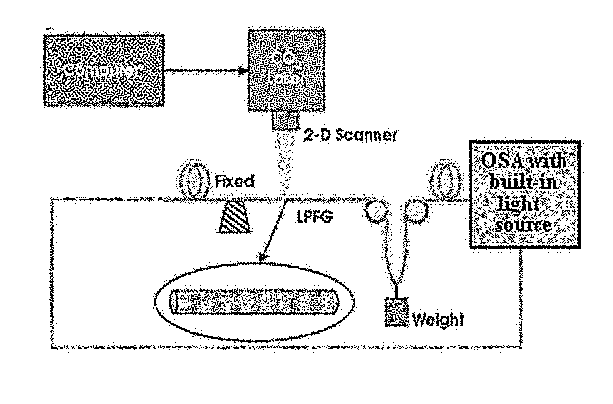
[0032]The fabrication system proposed in this invention, which is based on two dimensi...


PUM


Abstract

This invention relates to a sensor device consisting of long period gratings made of rare-earth doped double clad fiber, which is written by CO2 laser irradiation while the fiber is held static, for gamma dose measurement in the range of 150 Gy-2.5 kGy, extendable to 20 kGy, which measurements are real-time and can be from remote locations. The sensor device has high wavelength dip shift sensitivity of at least 2.8 nm / kGy, and its radiation-induced changes are near permanent. The gratings demonstrate negligible temperature sensitivity and the shifts recorded show negligible annealing at room temperature.

Description

FIELD OF THE INVENTION[0001]This invention relates primarily to fiber optic sensors, fiber lasers, radiation and food processing, reactors, nuclear waste treatment, X-ray sources amongst others.BACKGROUND OF THE INVENTION[0002]The current state of art for ionizing radiation-dose measurement in the range of 150 Gy-20 kGy (One Gray (1 Gy) corresponds to radiation absorbed dose equal to energy deposition of 1 Joule / kg. of material, 1 Gy=100 Rad) permits only off-line dose measurement. The currently used standard techniques used in industry are as follows:[0003]1. Sachets containing dyed Perspex (PMMA), which darkens quantitatively when irradiated, and when measured by spectrophotometry yields a precise measure of dose. In another version, a radio chromic film cast from polyvinyl butyral (PVB) resin mixed with proprietary dye is used. Ionizing radiation activates the dye centers and causes a predictable color change that is related to absorbed dose.[0004]2. Blister-packed pellets, which...

Claims


Application Information

Patent Timeline
15 Feb 2018
Publication
US20180045835A1
IPC
G01T1/02
CPC
G01T1/02; G01T1/023; G01T1/201
Inventors
KHER, SANJAY; CHAUBEY, SMITA