Thermoelectric heat energy recovery module

a technology of thermal energy recovery and thermal energy, which is applied in the direction of electric propulsion mounting, machine/engine, vehicle sub-unit features, etc., can solve the problems of less favorable t across the thermopile for the generation of electrical voltage, limit the types of materials that can be employed, and achieve the effect of reducing the back pressure of the exhaust system

Inactive Publication Date: 2018-03-01
QUANTUM INDUSTRIAL DEVELOPMENT CORP
View PDF7 Cites 7 Cited by
  • Summary
  • Abstract
  • Description
  • Claims
  • Application Information

AI Technical Summary

Benefits of technology

[0016]On the lateral side(s) of the module conduit, in close proximity to the outlet on the outer surface(s) edge, an aerodynamically contoured air foil may be affixed at an angle to direct air flow toward the area where the outlet is vented to the atmosphere. The air foil may tak

Problems solved by technology

Previous automotive applications of thermopiles have had limited success in part because the temperatures of exhaust gases from internal combustion engines can reach 800° C. when measured at the exhaust manifold.
Conventional heat sink materials, stable at these high temperatures, are not as thermally conductive as they are at lower temperatures resulting in less favorable ΔT across the thermopile for the generation of electrical voltage.
These higher exhaust gas temperatures limit the types of materials that can be employed to maintain favorable rates of efficient heat energy transfer.
None of the previous designs were s

Method used


Image

  • Thermoelectric heat energy recovery module
  • Thermoelectric heat energy recovery module
  • Thermoelectric heat energy recovery module

Examples


Embodiment Construction

Thermoelectric Heat Energy Recovery Module (THERMO) Generator for Application in a Stirling-Electric Hybrid Automobile

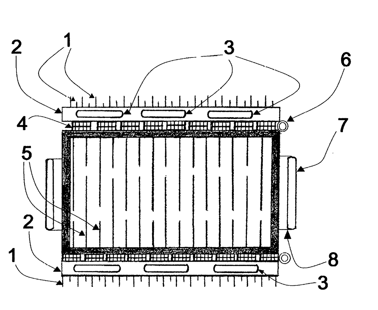
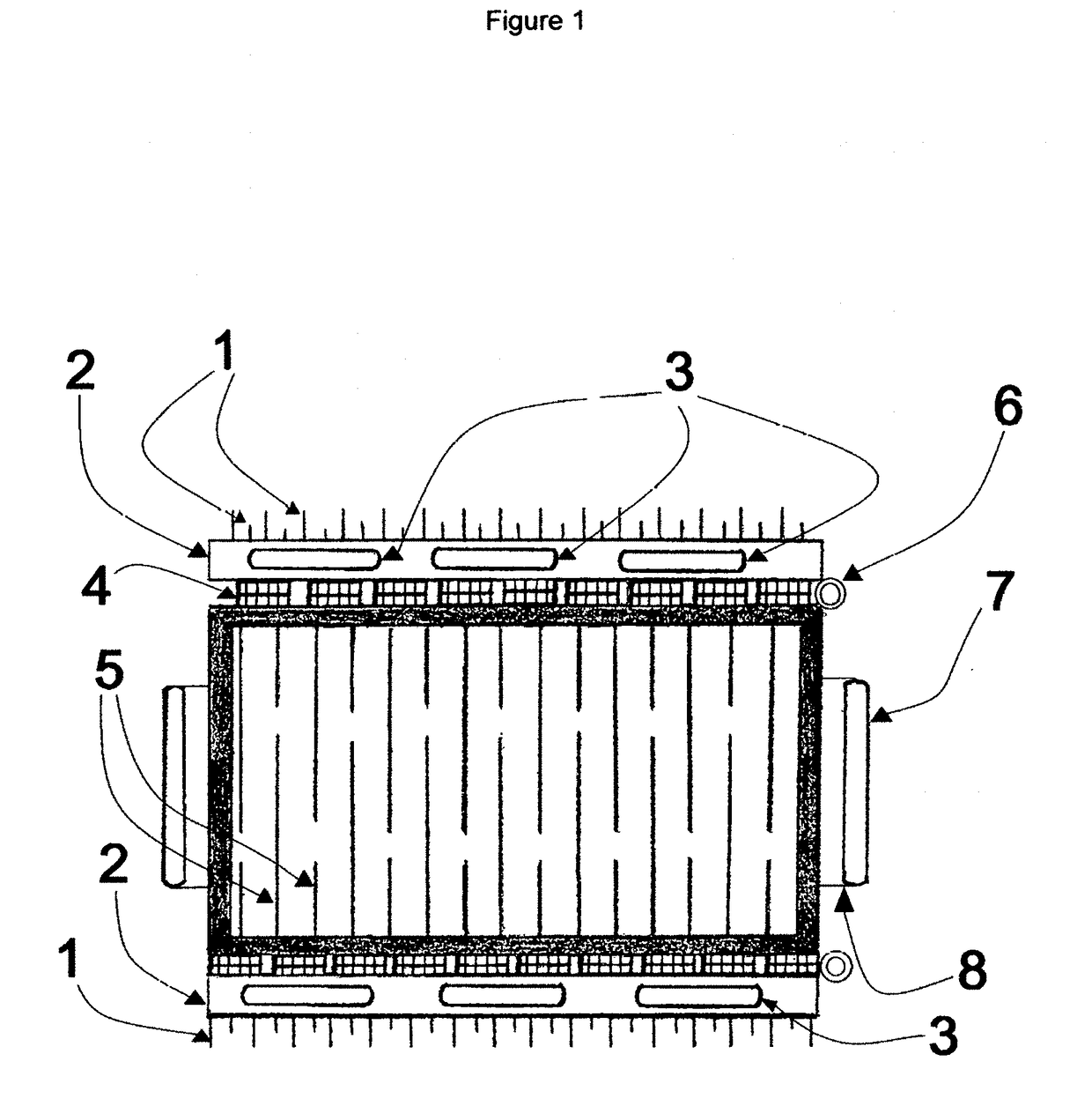
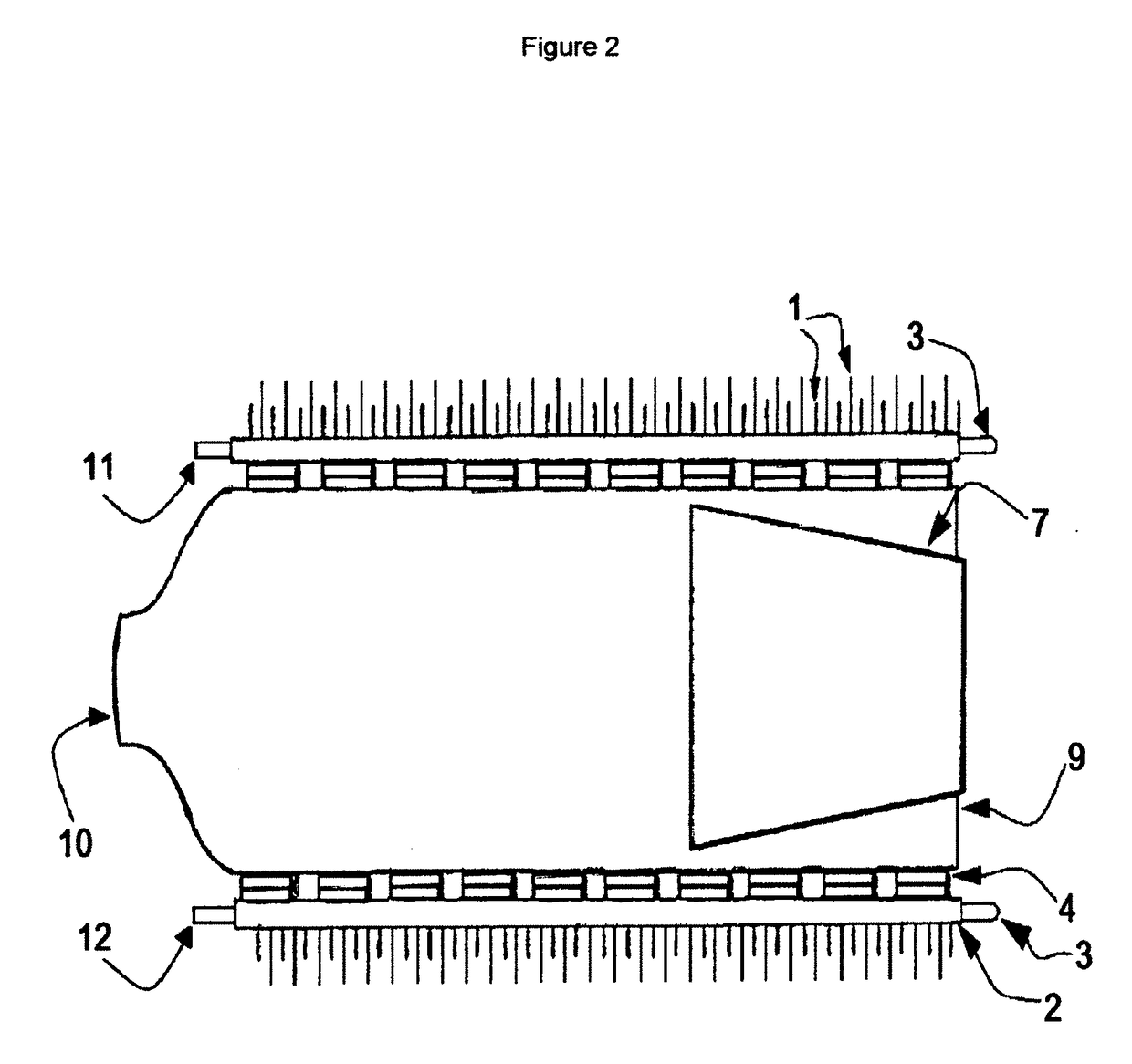
[0031]This embodiment of the invention is a Stirling-Electric Hybrid automotive exhaust module generator device for converting waste heat energy into electrical energy by employing the Thermoelectric Effect, also known as the Seebeck Effect. The disclosure herein describes how the invention converts heat energy, from hot exhaust gases, from the operation of an automotive external combustion engine (e. g. Stirling Cycle engine), into electrical energy which is fed back into the electrical system of the Stirling-Electric Hybrid Automobile (U.S. Pat. No. 7,726,130 B2) minimizing losses due to the second law of thermodynamics. The improvements on the art in this disclosure focus on taking advantage of the first law of thermodynamics by increasing residence time of the hot exhaust gases through the module conduit by employing heat sink(s), in the form of a plurality of pi...


PUM


Abstract

This embodiment is a Stirling-Electric Hybrid automotive exhaust module generator device for converting waste heat energy into electrical energy by employing the Seebeck Effect. The disclosure herein describes how the invention converts heat energy, from hot exhaust gases, from the operation of an automotive external combustion engine (e. g. Stirling Cycle engine), into electrical energy which is fed back into the electrical system of the Stirling-Electric Hybrid Automobile (U.S. Pat. No. 7,726,130 B2) minimizing losses due to the second law of thermodynamics. The improvements on the art in this disclosure focuses on employing a plurality of thermopiles and materials with improved coefficients of thermal conductivity and increasing residence time of the hot exhaust gases by inducing turbulent flow through the module generator device in conjunction with external cooling plate(s), heat sink(s); in the form of a plurality of pin(s), on the interior and exterior surface(s) of the module generator device.

Description

REFERENCES CITED[0001]Automotive Waste Heat Conversion to Electric power using Skutterudite, TAGS, PbTe and BiTe, LaGrandure et al. Visteon Corporation, 2006[0002]Thermal Conductivity of Selected Materials, Powell et al. National Bureau of Standards, 1966[0003]Thermoelectric Handbook, Micro to Nano, D. M. Rowe, 2006[0004]Disposition of Radioisotope Thermoelectric Generators Currently Located at the Oak Ridge National Laboratory, J. Glenn et al. WM2012 Conference, Feb. 26-Mar. 1, 2012U.S. PATENTS DOCUMENTS CITED[0005]U.S. Pat. No. 7,726,130 B2, Stirling-Electric Hybrid Automobile, McDowell, June, 2010 Research Collaboration Between[0006]Texas A&M University-San Antonio and Quantum Industrial Development Corp.BACKGROUND OF THE INVENTIONThe Field of the Invention[0007]The application of a thermopile module generator device to generate electrical energy from waste heat energy carried by exhaust gases from an external combustion Stirling-Electric Hybrid Automobile (ibid) is novel. Additi...

Claims


Application Information

Patent Timeline
IPC IPC(8): F01N5/02B60K6/26H01L35/30H01L35/32
CPCF01N5/025B60K6/26H01L35/30H01L35/325B60Y2200/92B60Y2400/206Y10S903/906B60K6/24F02G5/02Y02T10/12Y02T10/62H10N19/101H10N10/13B60K1/00
Inventor JUNIO, MARK A.MCCAULEY, TERRY R.MCDOWELL, JOSEPH S.WATTSON, VICTORIA A.
Owner QUANTUM INDUSTRIAL DEVELOPMENT CORP
Why Eureka
Try Eureka