Synchronous Detection Circuit And Method For Determining A Bio-Impedance Of A Biological Tissue

a bio-impedance and detection circuit technology, applied in the field of low energy, can solve the problems of reducing the accuracy of bio-impedance measurement, large phase errors, and large power consumption, and achieve the effects of low power consumption, high efficiency, and high accuracy and measurement reliability

Active Publication Date: 2018-03-08
SILICON LAB INC
View PDF3 Cites 22 Cited by
  • Summary
  • Abstract
  • Description
  • Claims
  • Application Information

AI Technical Summary

Benefits of technology

[0014]As described in more detail below, high efficiency and low power consumption are achieved in the embodiments of synchronous detection circuits described herein by extracting magnitude and phase information from only four digital samples per period of the output waveform. High accuracy and measurement reliability are achieved by resolving both the input waveform and the output waveform into M coarse points and N interpolation points per quadrant, and matching the OSR and the DR of the ADC to the input frequency of the input waveform.

Problems solved by technology

There are numerous problems associated with the synchronous detection circuit shown in FIG. 1.
In order to detect bio-impedance over such a wide range of frequencies, the bandwidth of the current driver 12 and the instrumentation amplifier 18 must be large, which leads to large power consumption.
This is difficult when analog filters are used, and is generally not done over a large number of frequencies, due to the increase in circuit complexity and size required for each additional frequency.
Any mismatch between the analog circuits within the two channels will cause large phase errors and reduce the accuracy of the bio-impedance measurement.
In addition, conventional techniques utilize two analog to digital converters operating simultaneously (one per I or Q channel) which is

Method used


Image

  • Synchronous Detection Circuit And Method For Determining A Bio-Impedance Of A Biological Tissue
  • Synchronous Detection Circuit And Method For Determining A Bio-Impedance Of A Biological Tissue
  • Synchronous Detection Circuit And Method For Determining A Bio-Impedance Of A Biological Tissue

Examples


Embodiment Construction

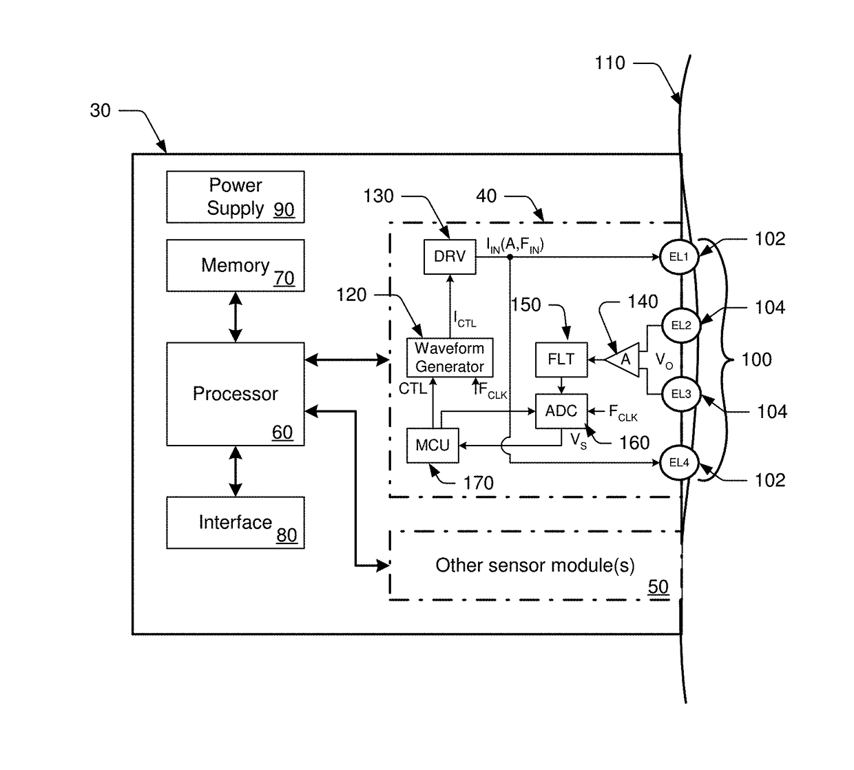
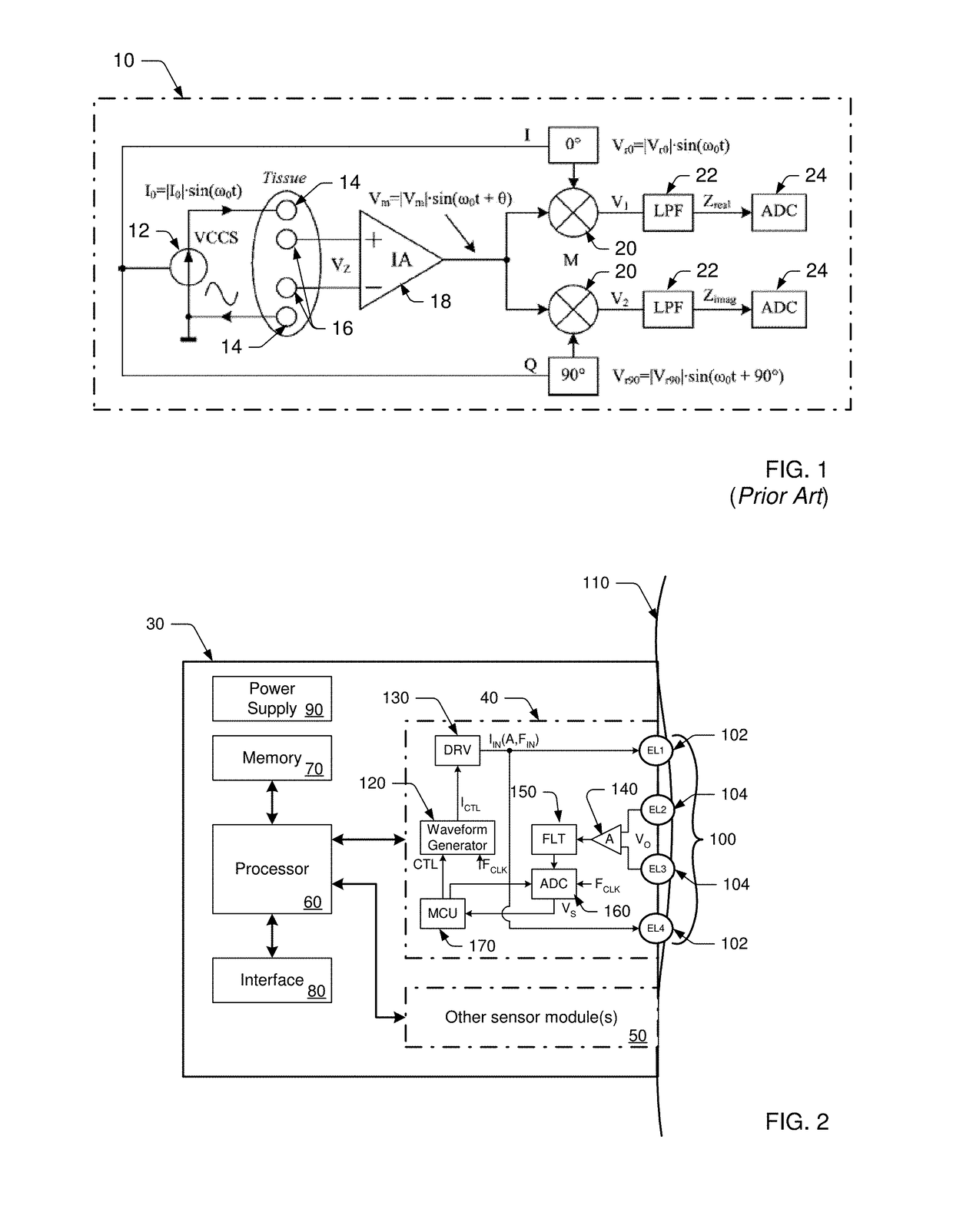
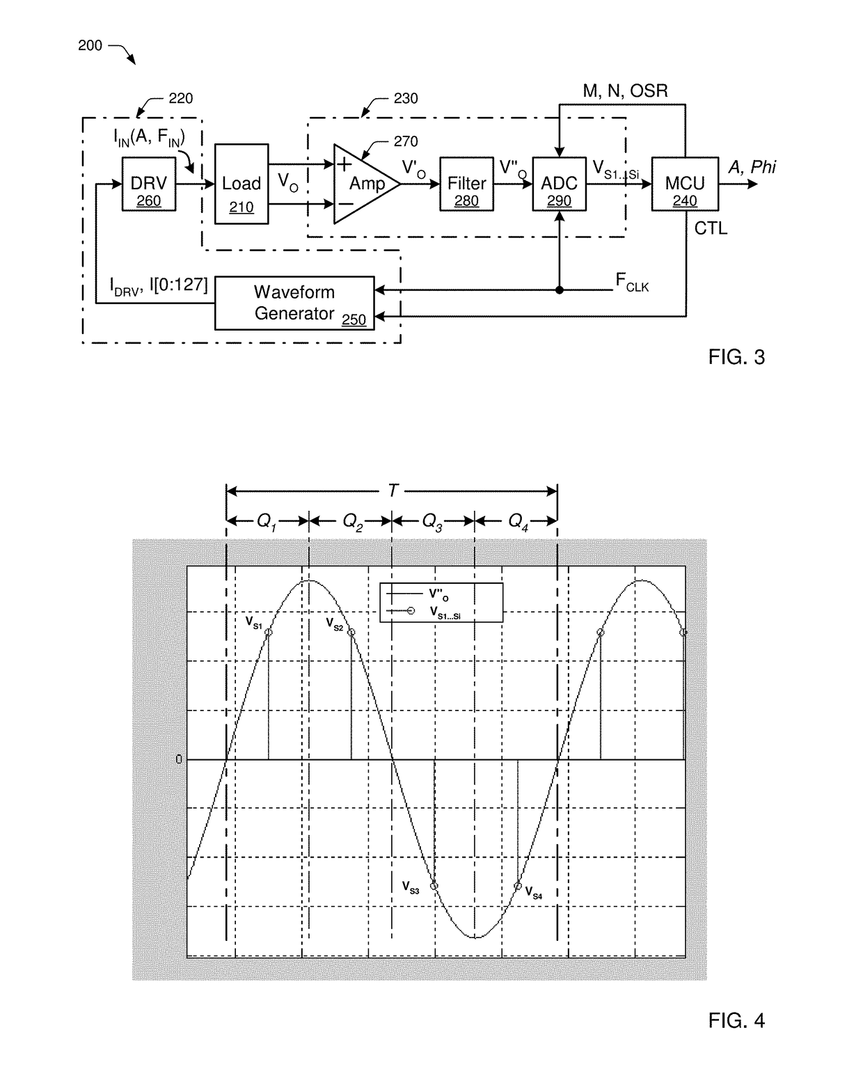
[0024]In general, the present disclosure is directed to synchronous detection circuits and methods for extracting magnitude and phase information from a waveform. Embodiments of the disclosed circuits and methods may be broadly used for extracting such information from substantially any amplitude and / or phase modulated signal. According to one embodiment, the disclosed circuits and methods may be used for extracting magnitude and phase information from a bio-impedance waveform. Regardless of application or use, the embodiments of synchronous detection circuits and methods disclosed herein provide a low power, low cost synchronous detection circuit, which demonstrates greater accuracy and measurement reliability than many currently available solutions.

[0025]According to one embodiment, the present disclosure may be directed to biometric monitoring devices, which are typically (although not exclusively) designed to be worn by a user continuously, intermittently or during certain activ...


PUM


Abstract

Embodiments of synchronous detection circuits and methods are provided for extracting magnitude and phase information from a waveform. One embodiment of a synchronous detection circuit includes a driver circuit, an analog-to-digital converter (ADC) and a controller. The driver circuit is configured to supply an input waveform at an input frequency to a load. The ADC is coupled to receive an output waveform from the load, and configured for generating four digital samples, each spaced 90° apart, for every period of the output waveform. The controller is configured for setting an oversampling rate (OSR) of the ADC, so that the ADC generates an integer number, M, of sub-samples for each digital sample generated by the ADC, where the integer number, M, of sub-samples is inversely proportional to the input frequency of the input waveform. The controller is further configured to use the digital samples generated by the ADC to extract magnitude and phase information from the output waveform.

Description

BACKGROUND1. Field of the Disclosure[0001]This disclosure relates to synchronous detection circuits and, more particularly, to a low-power, high accuracy synchronous detection circuit and method for determining a bio-impedance of a biological tissue.2. Description of the Relevant Art[0002]The following descriptions and examples are provided as background only and are intended to reveal information that is believed to be of possible relevance to the present disclosure. No admission is necessarily intended, or should be construed, that any of the following information constitutes prior art impacting the patentable character of the subject matter claimed herein.[0003]Electrical bio-impedance measurements have been widely used as a non-invasive technique for characterizing biological tissues, detecting heart rate, determining body composition, and ascertaining other physiological states and conditions. Bio-impedance is the opposition offered by biological tissues to the current flowing ...

Claims


Application Information

Patent Timeline
IPC IPC(8): G01N27/04G01R19/00A61B5/053A61B5/00A61B5/024A61B5/08
CPCG01N27/04G01R19/0038A61B5/0537A61B5/6801A61B5/7225A61B5/0816A61B5/6887A61B5/742A61B5/7475A61B5/0002A61B5/024A61B5/7278A61B5/053A61B5/0531A61B5/6802A61B5/6804A61B5/6831A61B5/6847A61B5/7203A61B5/7235A61B5/725G01R27/02G01R27/00G01R25/005
Inventor CHERKASSKY, ALEXANDERDEL SIGNORE, BRUCE P.
Owner SILICON LAB INC
Why Eureka
Try Eureka