Sensor fusion systems and methods for eye-tracking applications

Inactive Publication Date: 2018-03-08
VALVE
View PDF3 Cites 15 Cited by
  • Summary
  • Abstract
  • Description
  • Claims
  • Application Information

AI Technical Summary

Benefits of technology

The present invention is about a technique that combines two complementary tracking systems to create a high-frame-rate, low-latency, accurate eye-tracking system at a low cost. This technique allows for the benefits of both systems, providing both positional accuracy and relative data. This results in the best of both worlds, with accurate data at very low latency. Optical flow sensors can generate relatively accurate data, but may provide inaccurate positional information. Combining the slow system's positional accuracy with the fast system's relative data allows for the best of both worlds, resulting in accurate eye-tracking.

Problems solved by technology

In order to be non-invasive and keep costs down, consumer-grade eye tracking solutions currently known in the art have substantial limitations in terms of performance that prevent the system from being capable of knowing precisely or with low latency the location of the subject's pupil and gaze direction to take full advantage in the case of foveated rendering, and costly high-resolution high-frame-rate cameras may provide only limited benefits.
However, certain currently commercially available and relatively inexpensive camera image-based eye trackers for HMD applications are difficult to run at high frequency and with sufficiently low latency, and they may produce results that are noisy and prone to occlusion in certain implementations.
Although such systems may not necessarily be noisy because of low resolution or low frame rate, they may not sample at a sufficiently high rate to characterize the actual movement of the eye because they miss activity that takes place between samples or incorrectly determine beginning or end to saccades (rapid eye movements, discussed further below) and thus generate bad velocity and acceleration data causing error in predictions.
If an image does not move on the retina, the rods / cones on the person's retina may become desensitized to the image and the person effectively becomes blind to it.
It is also not generally possible to determine eye motion precisely unless measurements can be performed well enough to decide whether gaze change is a micro-saccade and the gaze is already reverting back onto the object of focus, or whether the eye is instead accelerating away with a voluntary saccade.
Thus, currently available VR camera-based eye-tracking solutions typically do not perform with enough responsiveness, accuracy, or robustness to realize all the potential value of eye tracking for use in a consumer class HMD device.
This is because increasing the frame rate and / or resolution of the eye-tracking camera is complex and expensive.
Even if possible, such improvements typically generate more data, which increase bandwidth and thus make transmission more difficult and cause additional central processing unit (“CPU”) and / or graphics processing unit (“GPU”) load to calculate gaze direction.
The extra load can either increase system cost or take limited computing time away from the application that is rendering on the display.
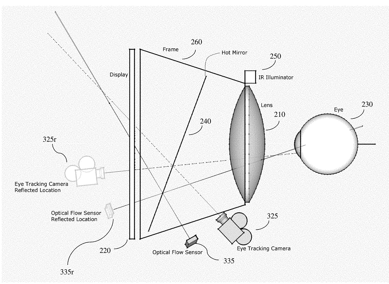
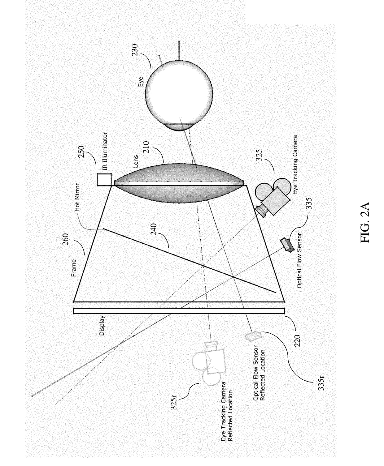
Another limitation is related to extreme eye angles, which may force the pupil or corneal reflections to go out of view of the camera in certain camera-based eye-tracking systems.
The relative motion data may contain slight errors which over time cause drift as the errors accumulate.
However, they typically exhibit low positional accuracy due to their known propensity to drift over time.
So while they can provide good relative information on how far a mouse has traveled over a surface over short intervals of time, they cannot tell where the mouse is on the surface or where it is relative to its starting position because small errors accumulate causing large discrepancies.
Combined with their low resolution and inability to “see” an entire user's eye or determine at any point where the eye is gazing, they cannot by themselves typically provide a sufficiently accurate position of the eye.

Method used


Image

  • Sensor fusion systems and methods for eye-tracking applications
  • Sensor fusion systems and methods for eye-tracking applications
  • Sensor fusion systems and methods for eye-tracking applications

Examples


Embodiment Construction

[0026]Those of ordinary skill in the art will realize that the following description of the present invention is illustrative only and not in any way limiting. Other embodiments of the invention will readily suggest themselves to such skilled persons, having the benefit of this disclosure, and the general principles defined herein may be applied to other embodiments and applications without departing from the spirit and scope of the present invention. Thus, the present invention is not intended to be limited to the embodiments shown, but is to be accorded the widest scope consistent with the principles and features disclosed herein. Reference will now be made in detail to specific implementations of the present invention as illustrated in the accompanying drawings. The same reference numbers will be used throughout the drawings and the following description to refer to the same or like parts.

[0027]The data structures and code described in this detailed description are typically stor...


PUM


Abstract

Eye-tracking systems and methods for use in consumer-class virtual reality (VR) / augmented reality (AR) applications, among other uses, are described. Certain embodiments combine optical eye tracking that uses camera-based pupil and corneal reflection detection with optical flow hardware running at a higher frequency. This combination provides the accuracy that can be attained with the former and at the same time adds the desirable precision and latency characteristics of the latter, resulting in a higher performing overall system at a relatively reduced cost. By augmenting a camera tracker with an array of optical flow sensors pointed at different targets on the visual field, one can perform sensor fusion to improve precision. Since the camera image provides an overall picture of eye position, that information can be used to cull occluded optical flow sensors, thus mitigating drift and errors due to blinking and other similar phenomena.

Description

BACKGROUND OF THE DISCLOSURE1. Field of the Disclosure[0001]The disclosure relates generally to computerized image processing, and more particularly to systems and methods for implementing sensor fusion techniques in computerized eye-tracking applications such as in head-mounted displays for virtual reality and / or augmented reality systems with improved features and characteristics.2. General Background[0002]One current generation of virtual reality (“VR”) experiences is created using head-mounted displays (“HMDs”), which can be tethered to a stationary computer (such as a personal computer (“PC”), laptop, or game console), combined and / or integrated with a smart phone and / or its associated display, or self-contained. VR experiences generally aim to be immersive and disconnect the users' senses from their surroundings.[0003]Generally, HMDs are display devices, worn on the head of a user, that have a small display device in front of one (monocular HMD) or each eye (binocular HMD).[00...

Claims


Application Information

Patent Timeline
IPC IPC(8): G06T7/00G06F3/01G06K9/00G06T7/20H04N5/33
CPCG06T7/0044G06F3/013G06K9/00604G06T2207/30201G06T7/2066H04N5/33G06T2207/10048G06T7/208G02B27/017G02B2027/0134G02B2027/0138G02B27/0093H04N13/383G06T7/277G06V40/19G06V10/803G06F18/251
Inventor MALAIKA, YASSERNEWELL, DAN
Owner VALVE
Why Eureka
Try Eureka