Single-drive rigid-flexible coupling precision motion platform and realization method and application thereof

a precision motion platform and rigid-flexible technology, applied in the field of single-drive rigid-flexible coupling precision motion platform and a realization, can solve the problems of affecting the execution accuracy of high-speed precision motion platform, affecting positioning accuracy, and uncertainty of amplitude of frictional resistan

Active Publication Date: 2018-04-19
GUANGDONG UNIV OF TECH
View PDF7 Cites 18 Cited by
  • Summary
  • Abstract
  • Description
  • Claims
  • Application Information

AI Technical Summary

Benefits of technology

[0022]1) the linear driver directly drives the core motion platform; when driving force does not overcome static friction of the rigid frame, the co

Problems solved by technology

Uncertain change of surface roughness between motion pairs in the high-speed precision motion platform causes uncertain change of amplitude of frictional resistance.
However, sudden change of the acceleration at a moment of the state switching is caused by a difference between a static friction coefficient and a moving friction coefficient, thereby causing “jitter” of the motion platform near a final position location and influencing positioning accuracy.
How to reduce a positioning error influence caused by switching of frictional states in the processes of starting, stop and micro feeding is an important problem that affects execution accuracy of the high-speed precision motion platform.
Because of such factors as microscopic property difference of contact surfaces, manufacturing errors and the like between the motion pairs, it is difficult to establish a highly accurate frictional force model, so that a complex compensation control method needs to be adopted in a motion control system.
Implementation cost of low-friction motion pairs of the air floatation b

Method used


Image

  • Single-drive rigid-flexible coupling precision motion platform and realization method and application thereof
  • Single-drive rigid-flexible coupling precision motion platform and realization method and application thereof
  • Single-drive rigid-flexible coupling precision motion platform and realization method and application thereof

Examples


Embodiment Construction

[0047]Technical solutions in embodiments of the present invention will be clearly and completely described in combination with drawings in embodiments of the present invention. Apparently, described embodiments are only part of embodiments of the present invention, not all of embodiments. All other embodiments obtained by those ordinary skilled in the art based on embodiments in the present invention without contributing creative labor belong to a protection scope of the present invention.

[0048]An embodiment A of a motion platform proposed by the present invention is as follows:

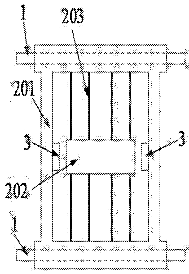
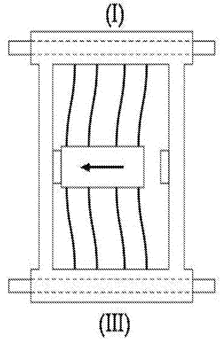
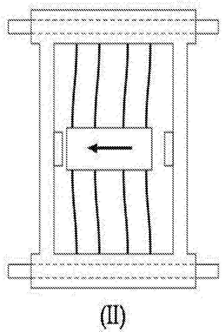
[0049]As shown in FIG. 1 to FIG. 3, the motion platform mainly consists of a machine base A4, a linear guide rail A101, a guide rail sliding block A102, a rigid frame A201, a core motion platform A202, flexible hinges A203, a grating displacement sensor A6, a linear motor driver and the like, wherein the rigid frame A201 is connected with the core motion platform A202 through flexible hinges A203 motion pairs...


PUM

PropertyMeasurementUnit
Flexibilityaaaaaaaaaa
Stiffnessaaaaaaaaaa

Abstract

The present invention discloses a single-drive rigid-flexible coupling precision motion platform, including a machine base, a linear guide rail, a rigid-flexible coupling motion platform, a linear driver and a displacement sensor, wherein the rigid-flexible coupling motion platform includes a rigid frame, flexible hinges and a core motion platform; and the core motion platform of the rigid-flexible coupling motion platform is connected with the rigid frame through the flexible hinges. In this arrangement, the single-drive rigid-flexible coupling precision motion platform disclosed by the present invention can realize high-accuracy continuous change displacements of the platform, thereby avoiding displacement “jitter” caused by sudden change of acceleration. The present invention further discloses a realization method and an application including the above platform.

Description

CROSS-REFERENCE TO RELATED APPLICATIONS[0001]This application is a continuation of International Patent Application No. PCT / CN2016 / 093259 with a filing date of Aug. 4, 2016, designating the United States, now pending, and further claims priority to Chinese Patent Application No. CN201610508540.X with a filing date of Jun. 29, 2016. The content of the aforementioned applications, including any intervening amendments thereto, are incorporated herein by reference.TECHNICAL FIELD[0002]The present invention relates to motor driving technologies, and particularly relates to a single-drive rigid-flexible coupling precision motion platform and a realization method and an application thereof.BACKGROUND OF THE PRESENT INVENTION[0003]A high-speed precision motion platform is widely used in the fields of semiconductor encapsulation and the like. Uncertain change of surface roughness between motion pairs in the high-speed precision motion platform causes uncertain change of amplitude of friction...

Claims


Application Information

Patent Timeline
IPC IPC(8): B23Q1/34H01L21/67B81C1/00
CPCB23Q1/34H01L21/67126B81C1/00126B23Q5/28B23Q1/58B23Q1/25B23Q1/36H02K41/02B23Q2210/002B81C1/00
Inventor YANG, ZHIJUNBAI, YOUDUNCHEN, XINCHEN, CHAORAN
Owner GUANGDONG UNIV OF TECH
Why Eureka
Try Eureka