

Interpolation Measurement of the Arrival Time and/or Amplitude of a Digitized Electronic Pulse
a technology of digitized electronic pulses and interpolation, which is applied in the direction of pulse characteristics measurement, instruments, horology, etc., can solve the problems of reducing timing accuracy, adding further errors, and limited methods
- Summary
- Abstract
- Description
- Claims
- Application Information
AI Technical Summary
Benefits of technology
Problems solved by technology
Method used
Image

Examples
Embodiment Construction
122.122.1.Hardware Considerations122.2.Investigation of errors in digital constant fraction discrimination122.3.An accurate digital constant fraction discrimination method142.3.1.General approach152.3.2.Implementation using fitting methods152.3.3.Implementation using convolution methods162.3.4.Preferred convolution method172.3.5.Finding the maximum M182.3.6.Finding φ and tA192.4.Results 1: laser-illuminated PMTs - fast pulses202.5.Results 2: 60Co irradiated LaBr3 crystals - semi-fast pulses212.6.Implementation232.7.An accurate digital amplitude measurement method242.8.Results 3: laser-illuminated PMTs - fast trigger pulses242.9.Results 4: 60Co irradiated LaBr3 crystals - semi-fast pulses252.10.Discussion253.References254.Conclusions27What is Claimed is:29Abstract of the Disclosure33
CROSS REFERENCE TO RELATED APPLICATIONS
[0002]This application is related to U.S. patent application Ser. No. ______, filed contemporaneously with this application, for “Ratio-Reference Measurement of the ...
PUM
 Abstract
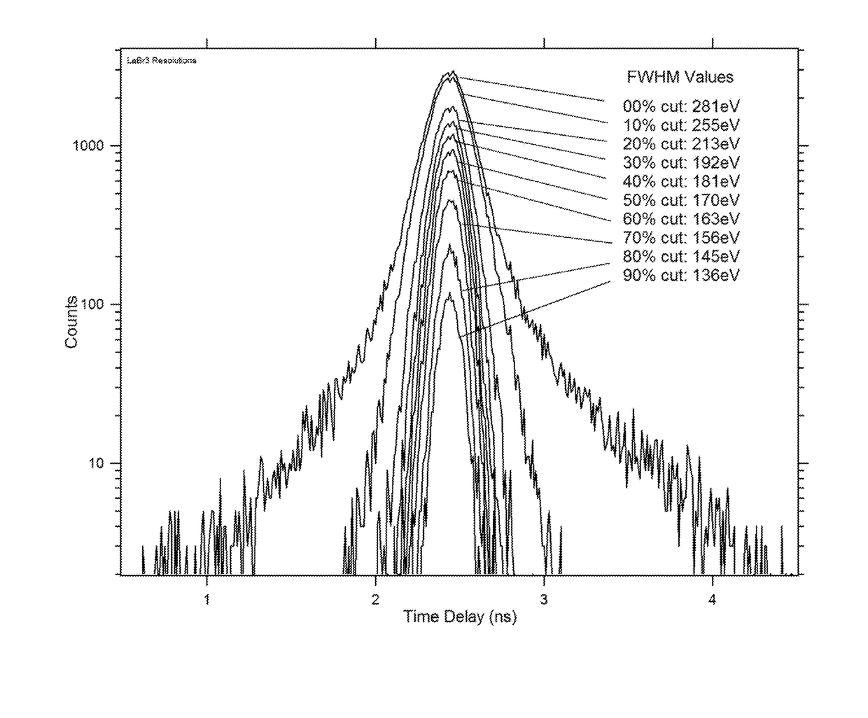
Description
Claims
Application Information