Backlight module
- Summary
- Abstract
- Description
- Claims
- Application Information
AI Technical Summary
Benefits of technology
Problems solved by technology
Method used
Image

Examples
experiment example 1
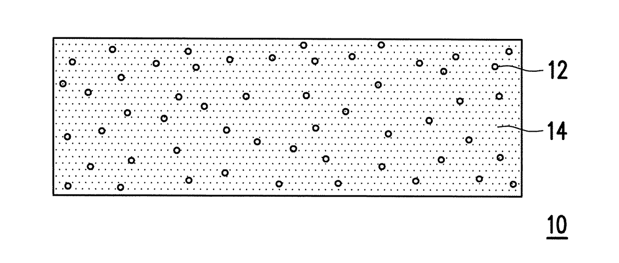
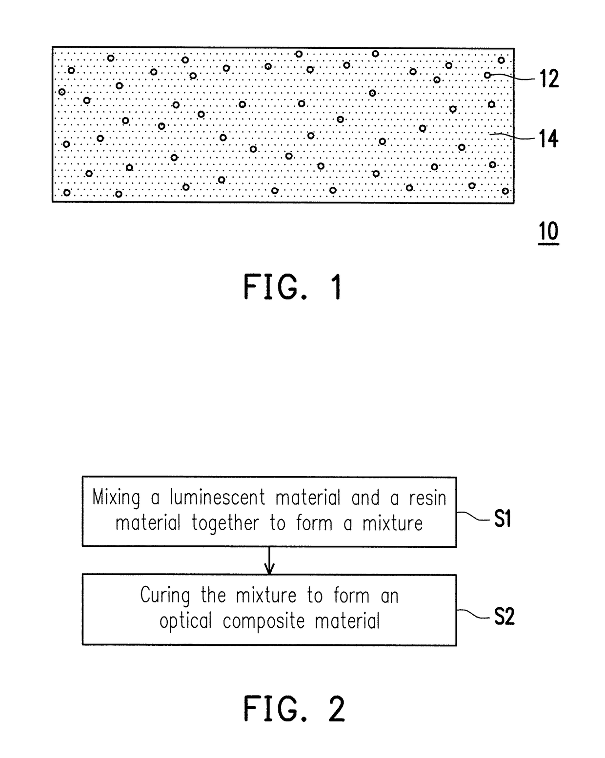
[0073]Firstly, all the components in Table 1 were mixed together to form a mixture. The mixture was then subjected to ultrasonic vibration in the dark for 30 minutes to 90 minutes, so that CdSe / ZnS quantum dots were uniformly dispersed in the mixture. Then, the mixture was filled between two polyethylene terephthalate (PET) substrates, followed by irradiation with ultraviolet light (370 nm, 400 W, 1 minute) to form an optical film.
TABLE 1LuminescentAcrylateAcrylatematerialSurfactantmonomeroligomerCross-linkerInitiatorCdSe / ZnSTris[2-(3-mercapto-2-phenylethylNeopentyl[2[1,1-dimethyl-Diphenyl(2,4,6-propionyloxy)ethyl]isocyanuratemethacrylateglycol2-[(1-oxoallyl)oxy]ethyl]-trimethylbenzoyl)-propoxylate5-phosphinediacrylateethyl-1,3-dioxan-oxide5-yl]methylacrylate5%13%49%16%16%1%
experiment example 2
[0074]In Experiment Example 2, the preparation method of the optical composite material was the same as the method described in Experiment Example 1 except that the components of the optical composite material and their proportions were different from those in Experiment Example 1.
[0075]The components of the optical composite material of Experiment Example 2 and their proportions were as shown in Table 2 below.
TABLE 2LuminescentAcrylateAcrylatematerialSurfactantmonomeroligomerCross-linkerInitiatorCdSe / ZnSGlycol2-phenylethyl1,6-hexanediol[2[1,1-dimethyl-Diphenyl(2,4,6-dimercaptomethacrylatedimethacrylate2-[(1-oxoallyl)oxy]ethyl]-trimethylbenzoyl)-acetate5-ethyl-1,3-dioxan-phosphine5-yl]methylacrylateoxide10%16%49%16%8%1%
[0076]The above components were mixed together according to the proportions provided in Table 2. Then, the optical composite material was dotted onto a blue light (450 nm) LED chip, followed by irradiation with ultraviolet light (370 nm, 400 W, 3 minutes) to cure the ...
experiment example 3
[0077]In Experiment Example 3, the preparation method of the optical composite material was the same as the method described in Experiment Example 1 except that the components of the optical composite material and their proportions were different from those in Experiment Example 1.
[0078]The components of the optical composite material of Experiment Example 3 and their proportions were as shown in Table 3 below.
TABLE 3LuminescentAcrylateAcrylatematerialSurfactantmonomeroligomerCross-linkerInitiatorCdSe / ZnSTrimethylolpropane-CyclicTriallyisocyanurateDiallylDiphenyl(2,4,6-trimercapto-trimethylolpropanephthalatetrimethylbenzoyl)-acetateformalphosphineacrylateoxide15%15%38%24%6%2%
[0079]A resultant mixture obtained by mixing the above components was filled into a transparent acrylic tube having an outer diameter of 16 mm and an inner diameter of 13 mm, followed by irradiation with ultraviolet light (370 nm, 400 W, 3 minutes) to cure the mixture.
[0080]From Experiment Examples 1 to 3, it is...
PUM
 Abstract
Description
Claims
Application Information
 - R&D
- Intellectual Property
- Life Sciences
- Materials
- Tech Scout
- Unparalleled Data Quality
- Higher Quality Content
- 60% Fewer Hallucinations
Browse by: Latest US Patents, China's latest patents, Technical Efficacy Thesaurus, Application Domain, Technology Topic, Popular Technical Reports.
© 2025 PatSnap. All rights reserved.Legal|Privacy policy|Modern Slavery Act Transparency Statement|Sitemap|About US| Contact US: help@patsnap.com