Smartcards, RFID devices, wearables and methods

a smartcard and rfid technology, applied in the direction of loop antennas, radiating element structural forms, instruments, etc., can solve the problems of reducing the effective magnetic field, reducing the power delivery to the chip, and unsuitable coupling frames, etc., to enable contactless communication, and improve coupling frames performan

Active Publication Date: 2018-05-03
AMATECH GRP LTD
View PDF0 Cites 39 Cited by
  • Summary
  • Abstract
  • Description
  • Claims
  • Application Information

AI Technical Summary

Benefits of technology

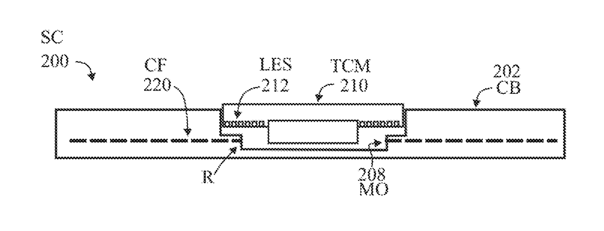
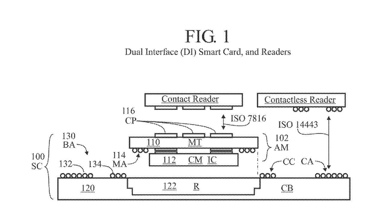
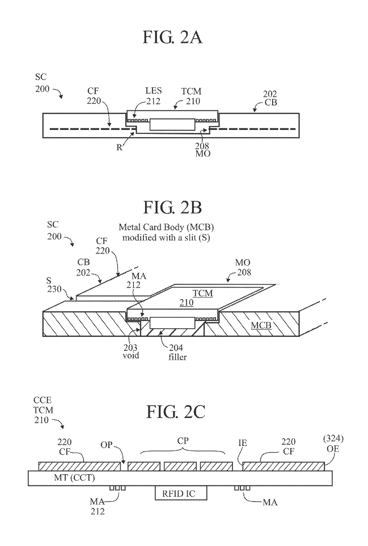
[0068]Coupling frames (CF) in combination with transponder chip modules (TCMs) may provide for inductive and capacitive coupling (so-called reactive coupling) with a contactless reader or point of sale terminal, or another RFID device. Coupling frames (CF) in combination with transponder chip modules (TCMs) may enhance (including enable) contactless communication between an RFID device and a contactless terminal (or other RFID device).
[0069]It is an object of the invention to provide improved coupling frames (CF), improved performance of coupling frames (CF), improved techniques for tuning coupling frames (CF)—for example, using capacitors—and to provide improved coupling of coupling frames to other coupling frames using component devices.
[0070]The use of a component device such as a capacitor across the slit of a coupling frame or multiple coupling frames having a capacitor connected across each slit may be used to improve the voltage delivery to the RFID chip, and to regulate the frequency response, bandwidth and Q factor of the complete system.
[0071]It is a further object of the invention to improve performance by stacking coupling frames, by surrounding a transponder device with a coupling frame or several coupling frames, by integrating coupling frames on a common substrate such as a glass epoxy tape, by overlapping a flexible circuit coupling frame incorporating a transponder device with a metal coupling frame, and by placing coupling frames adjacent to other coupling frames. Such coupling frame configurations may also include the connection of a component device (such as a capacitor) across the slit of each individual coupling frame.

Problems solved by technology

Further-more, reduction of the effective magnetic field reduces the power delivery to the chip.
While a metal foil significantly thinner than 0.03 μm can be transparent to electromagnetic waves and thus unsuitable as a coupling frame.
In addition, it is observed that the performance of the device is largely unaffected by the placement of additional coupling frames in close proximity.

Method used


Image

  • Smartcards, RFID devices, wearables and methods
  • Smartcards, RFID devices, wearables and methods
  • Smartcards, RFID devices, wearables and methods

Examples


Embodiment Construction

[0169]Various embodiments (or examples) may be described to illustrate teachings of the invention(s), and should be construed as illustrative rather than limiting. It should be understood that it is not intended to limit the invention(s) to these particular embodiments. It should be understood that some individual features of various embodiments may be combined in different ways than shown, with one another. Reference herein to “one embodiment”, “an embodiment”, or similar formulations, may mean that a particular feature, structure, operation, or characteristic described in connection with the embodiment is included in at least one embodiment of the present invention. Some embodiments may not be explicitly designated as such (“an embodiment”).

[0170]The embodiments and aspects thereof may be described and illustrated in conjunction with systems, devices and methods which are meant to be exemplary and illustrative, not limiting in scope. Specific configurations and details may be set ...


PUM


Abstract

Coupling frames comprising a conductive (metal) surface with a slit (S) or non-conductive stripe (NCS) extending from an outer edge to an inner position thereof, and overlapping a transponder device. A coupling frame with slit for coupling with an inductive or capacitive device (inductor or capacitor) may be used at any ISM frequency band to concentrate surface current around the slit. The coupling frame can be tuned to operate at a frequency of interested by introducing a resistive, inductive or capacitive element. The resonance frequency of the coupling frame can be matched to that of the transponder chip module to achieve optimum performance. Coupling frames with or without a transponder device may be integrated, overlapping, stacked or placed adjacent to one another to enhance system performance. Multiple coupling frames may be electrically isolated from one another by the application of a dielectric coating such Diamond Like Carbon (DLC).

Description

CROSS REFERENCE TO RELATED APPLICATIONS[0001]Priority (benefit of earlier filing date) is claimed, as a nonprovisional or continuation-in-part (“CIP”) of the following, all of which are incorporated by reference herein.a nonprovisional of U.S. 62 / 371,768 filed 7 Aug. 2016a nonprovisional of U.S. 62 / 483,329 filed 8 Apr. 2017a nonprovisional of U.S. 62 / 500,618 filed 3 May 2017a nonprovisional of U.S. 62 / 403,148 filed 2 Oct. 2016a continuation-in-part of U.S. Ser. No. 15 / 072,356 filed 17 Mar. 2016, which is[0002]a nonprovisional of U.S. 62 / 300,906 filed 28 Feb. 2016[0003]a nonprovisional of U.S. 62 / 289,189 filed 30 Jan. 2016[0004]a nonprovisional of U.S. 62 / 281,209 filed 21 Jan. 2016[0005]U.S. Ser. No. 15 / 072,356 filed 17 Mar. 2016 is also a continuation-in-part of U.S. Ser. No. 14 / 862,119 filed 22 Sep. 2015 (U.S. Pat. No. 9,697,459, 4 Jul. 2017), which is a nonprovisional of . . .[0006]U.S. 62 / 136,644 filed 23 Mar. 2015[0007]U.S. 62 / 150,307 filed 21 Apr. 2015[0008]U.S. 62 / 163,962 file...

Claims


Application Information

Patent Timeline
Patent Type & Authority Applications(United States)
IPC IPC(8): H01Q1/22H01Q7/00H01Q1/38G06K19/077
CPCH01Q1/2225H01Q7/005H01Q1/38G06K19/07773
Inventor FINN, DAVIDLOTYA, MUSTAFAMOLLOY, DARREN
Owner AMATECH GRP LTD
Why Eureka
Try Eureka