Particle collecting apparatus

a technology of collecting apparatus and particles, which is applied in the field of collecting apparatuses for collecting particles, can solve the problems of difficult collection of particles with a small size, unsuitable collection methods, and considerable collection time, and achieve the effects of short time, efficient collection of particles, and improved analysis work efficiency

Inactive Publication Date: 2018-05-10
SHIMADZU CORP
View PDF5 Cites 5 Cited by
  • Summary
  • Abstract
  • Description
  • Claims
  • Application Information

AI Technical Summary

Benefits of technology

[0025]According to the particle collecting apparatus according to the invention, it is possible to efficiently collect particles in a wide particle diameter range including significantly small-sized

Problems solved by technology

However, the above-described conventional collection methods have the following problems.
Even though the aerodynamic collection method is simple, since an inertial force of a particle decreases as a size of the particle decreases, a particle having a small size is difficult to collect.
For this reason, this collection method is unsuitable for collecting a small particle having a nanoscale particle d

Method used


Image

  • Particle collecting apparatus
  • Particle collecting apparatus
  • Particle collecting apparatus

Examples


first embodiment

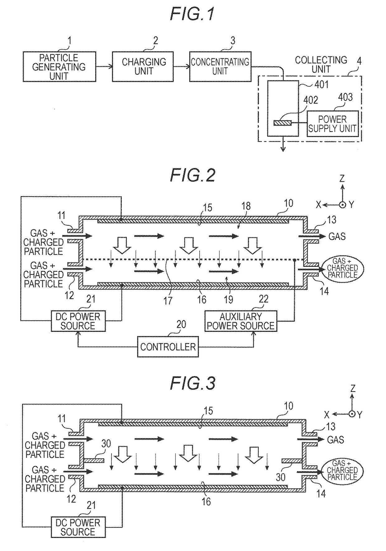
[0036]As illustrated in FIG. 1, the particle collecting apparatus of the first embodiment includes a particle generating unit 1, a charging unit 2, a concentrating unit 3, and a collecting unit 4.

[0037]For example, the particle generating unit 1 is an electrospray type aerosol generator, and generates minute particles to be analyzed in a gas phase. The particle generating unit 1 may correspond to an aerosol generator of another type, or may be replaced with a sample introducing unit for introducing previously sampled atmospheric air including aerosols. A gas flow containing minute particles to be analyzed is supplied from the particle generating unit 1 to the charging unit 2. In this instance, a carrier gas used for carrying the minute particles corresponds to atmospheric air, synthetic air, nitrogen gas, etc.

[0038]The charging unit 2 charges minute particles in introduced gas using various discharges such as corona discharge, arc discharge, spark discharge, dielectric barrier disch...

second embodiment

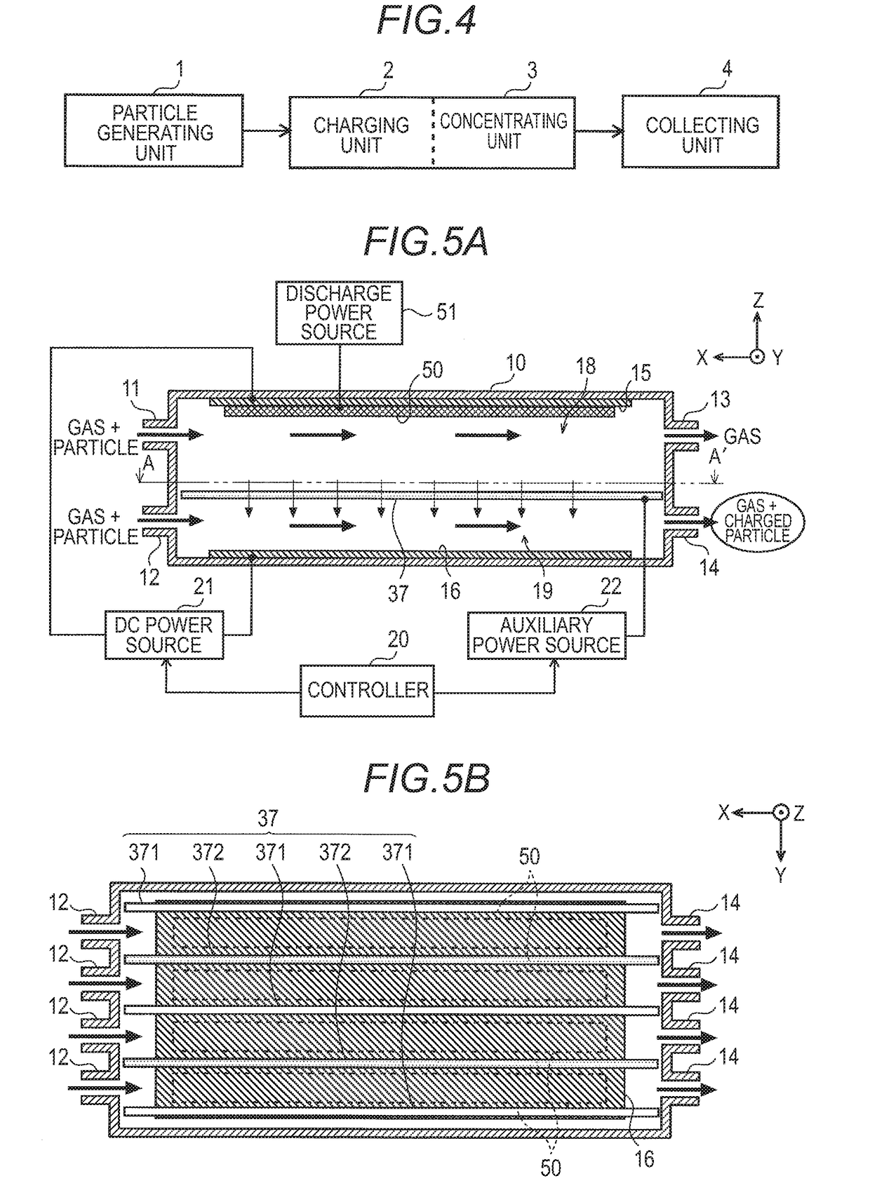
[0049]As illustrated in FIG. 4, in the particle collecting apparatus of the second embodiment, a charging unit 2 and a concentrating unit 3 are substantially integrated with each other. Further, gas containing minute particles is received to charge particles in a gas phase state, and the charged particles immediately after charging are concentrated and delivered to a collecting unit 4.

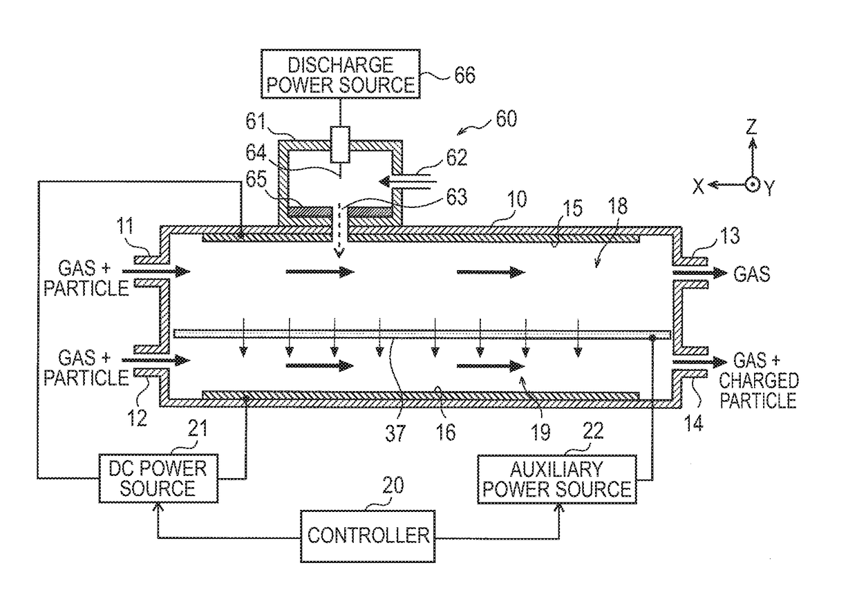
[0050]FIG. 5A is a schematic configuration diagram of the charging unit 2 / the concentrating unit 3 in the particle collecting apparatus of the second embodiment, and FIG. 5B is a cross-sectional view taken along A-A′ line of FIG. 5A. FIG. 6 is a perspective view of a filter 37 of the charging unit 2 / the concentrating unit 3 illustrated in FIG. 5A.

[0051]In the charging unit 2 / the concentrating unit 3, a carrier gas containing minute particles that are not charged is supplied into a casing 10 through a first gas introduction port 11 and a second gas introduction port 12, the minute particles are charged ...


PUM


Abstract

Minute particles in a gas generated in a particle generating unit are charged by a charging unit. A concentrating unit concentrates charged particles in an introduced gas, and a collecting unit absorbs and collects the concentrated charged particles on a sample plate by an electrostatic force. In the concentrating unit, the charged particles are concentrated by decreasing a flow rate of a gas (carrier gas) in which particles are dispersed while maintaining the number of introduced charged particles. When the flow rate of the gas decreases, and spatial density of the particles increases, it is possible to efficiently collect charged particles on the small sample plate in the collecting unit, and to shorten a collection time.

Description

FIELD OF THE INVENTION[0001]The present invention relates to a particle collecting apparatus that collects minute particles in gas on a plate to analyze the minute particles.BACKGROUND[0002]A minute liquid or solid particle floating in gas is referred to as an aerosol. Many of pollutants in automobile exhaust gas or smoke discharged from a factory are aerosols. In particular, there is concern about an influence of a so-called nano aerosol whose particle size is smaller than 1 μm on health. As a result, analysis of a size, a shape, a component, etc. of the aerosol is significantly important in a field of environmental measurement / evaluation, etc.[0003]Various analyzers such as an atomic force microscope (AFM), an electron probe X-ray micro-analyzer (EPMA), a transmission electron microscope (TEM), a scanning electron microscope (SEM), time-of-flight secondary ion mass spectrometry (TOF-SIMS), X-ray photoelectron spectroscopy (XPS), a fluorescence microscope, etc. have been used for a...

Claims


Application Information

Patent Timeline
IPC IPC(8): G01N1/22B08B15/00
CPCG01N1/2208B08B15/00G01N2001/2223G01N15/00G01N2015/0038G01N1/2247G01N1/40G01N2001/4038
Inventor SEKI, HIROSHIUENO, YOSHIHIROOKUDA, HIROSHISAKURAI, HIROMU
Owner SHIMADZU CORP
Why Eureka
Try Eureka