
Cobalt deposition selectivity on copper and dielectrics

Active Publication Date: 2018-05-10
ENTEGRIS INC
View PDF0 Cites 5 Cited by
  • Summary
  • Abstract
  • Description
  • Claims
  • Application Information

AI Technical Summary

Benefits of technology

The present disclosure relates to non-oxygen-containing cobalt precursors that can be used to form cobalt on various substrates, such as copper and dielectric materials. These precursors can be volatilized and contacted with a substrate to deposit cobalt thereon. The process involves vapor deposition conditions that allow for selective deposition of cobalt on the metal-containing surface of the substrate while avoiding defects. The disclosure also includes methods for reducing defects in cobalt that is vapor deposited on a base metal or tungsten surface, as well as a via fill process for forming cobalt in a via on a copper surface. The technical effects of the patent text include improved methods for depositing cobalt on various substrates with reduced defects and improved quality.

Problems solved by technology

Carbonyls, however, are not optimum precursors due to the formation of CO as a by-product in the vapor deposition.
Furthermore, the oxygen in the carbonyl may react with copper and form oxide in the cobalt / copper interface that degrades the EM resistance.

Method used


Image

  • Cobalt deposition selectivity on copper and dielectrics
  • Cobalt deposition selectivity on copper and dielectrics
  • Cobalt deposition selectivity on copper and dielectrics

Examples


example 1

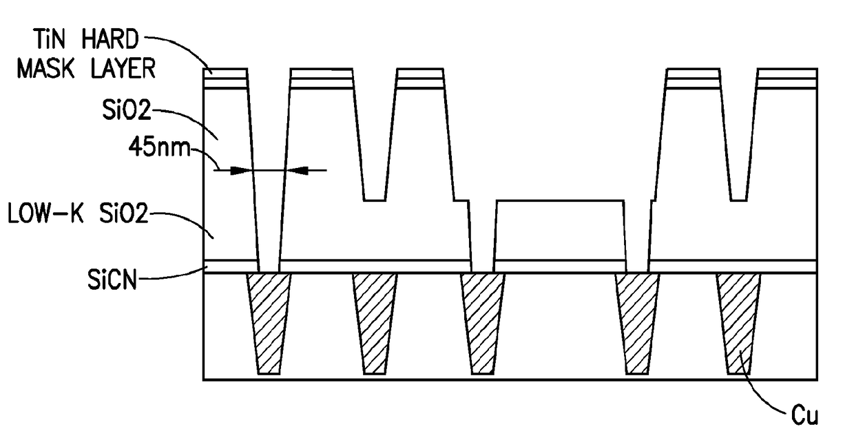
[0114]Cobalt deposition selectivity was evaluated, using Co(tBUNCHCHNtBu) precursor, on silicon dioxide, copper, and ULK substrate surfaces, at “C”, “L”, and “BL” positions on the substrate surface. Initial deposition runs were carried out at temperatures of 290° C., 250° C,, and 200° C., with the results shown in Table 1 below. Position “L” showed a lower deposition rate. Thickness of the deposited cobalt film, in Ångströms, was determined by x-ray fluorescence (XRF).

TABLE 1SubstratePositionTemperature (C.)XRF Thickness (A)SiO2C290113.8CopperBL290230.4SiO2C2503.6CopperL250121ULKC2000CopperL200170

[0115]Next, selectivity was evaluated at temperature of 290° C., 250° C., 200° C., and 150° C., on silicon dioxide, copper, and ULK substrate surfaces, at “C”, “L”, and “BL” positions on the substrate surface using Co(tBUNCHCHNtBu) precursor. The precursor flow rate was 50 μmole / minute, with hydrogen being flowed to the contacting operation at the rate of 0.5 L per minute as a co-flow gas w...

example 2

[0117]The characteristics of Co(tBuNCHCHNtBu)2, or Co(tBuDAD)2, were evaluated in a series of tests.

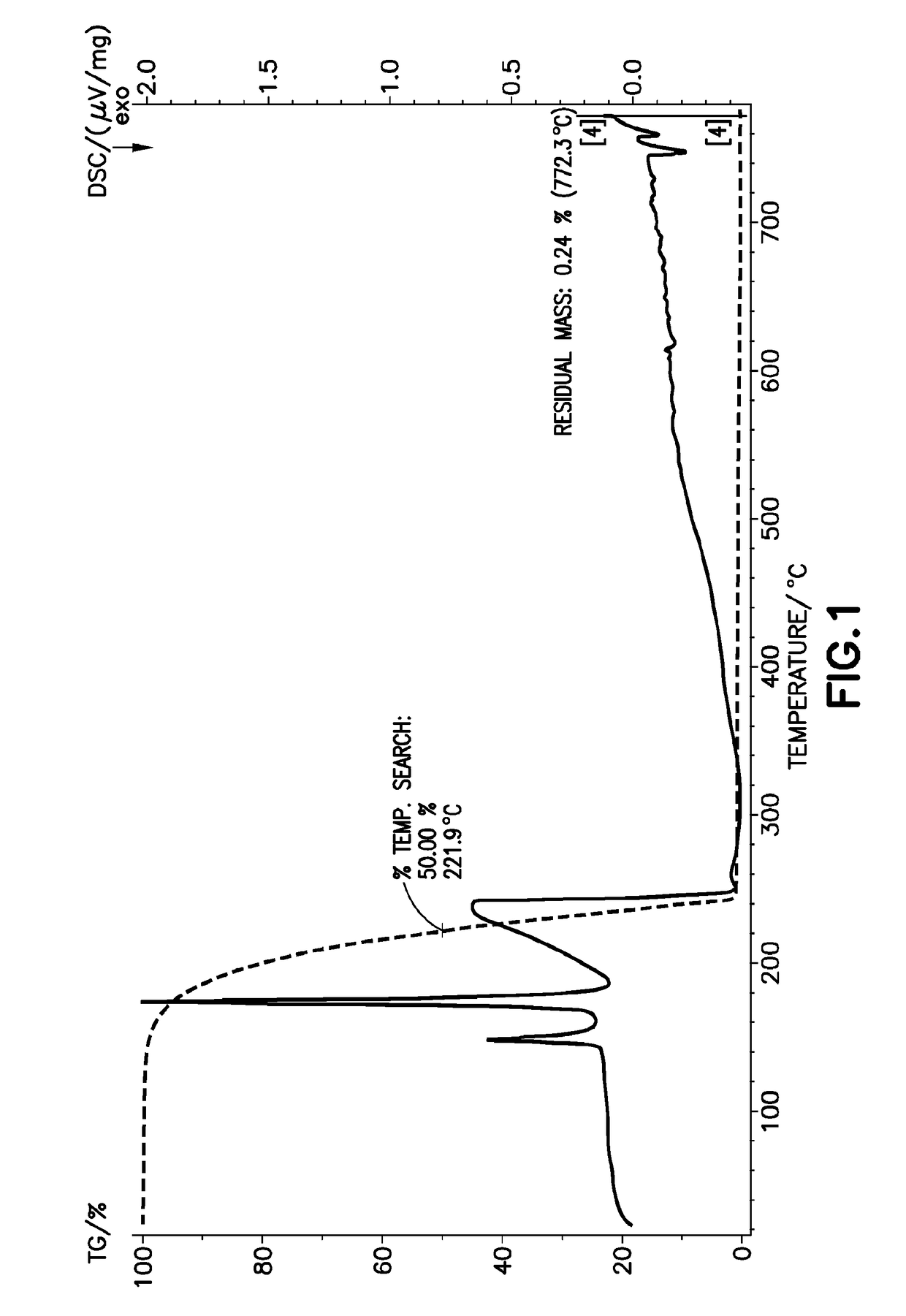
[0118]The thermogravimetric and differential scanning calorimetry characteristics of Co(tBuNCHCHNtBu)2 were determined by corresponding TG / DSC analysis, generating the thermal characteristics plot shown in FIG. 1, showing a T50 value of 221.9° C., and a residual mass value of 0.2% at temperature of 772.3° C.

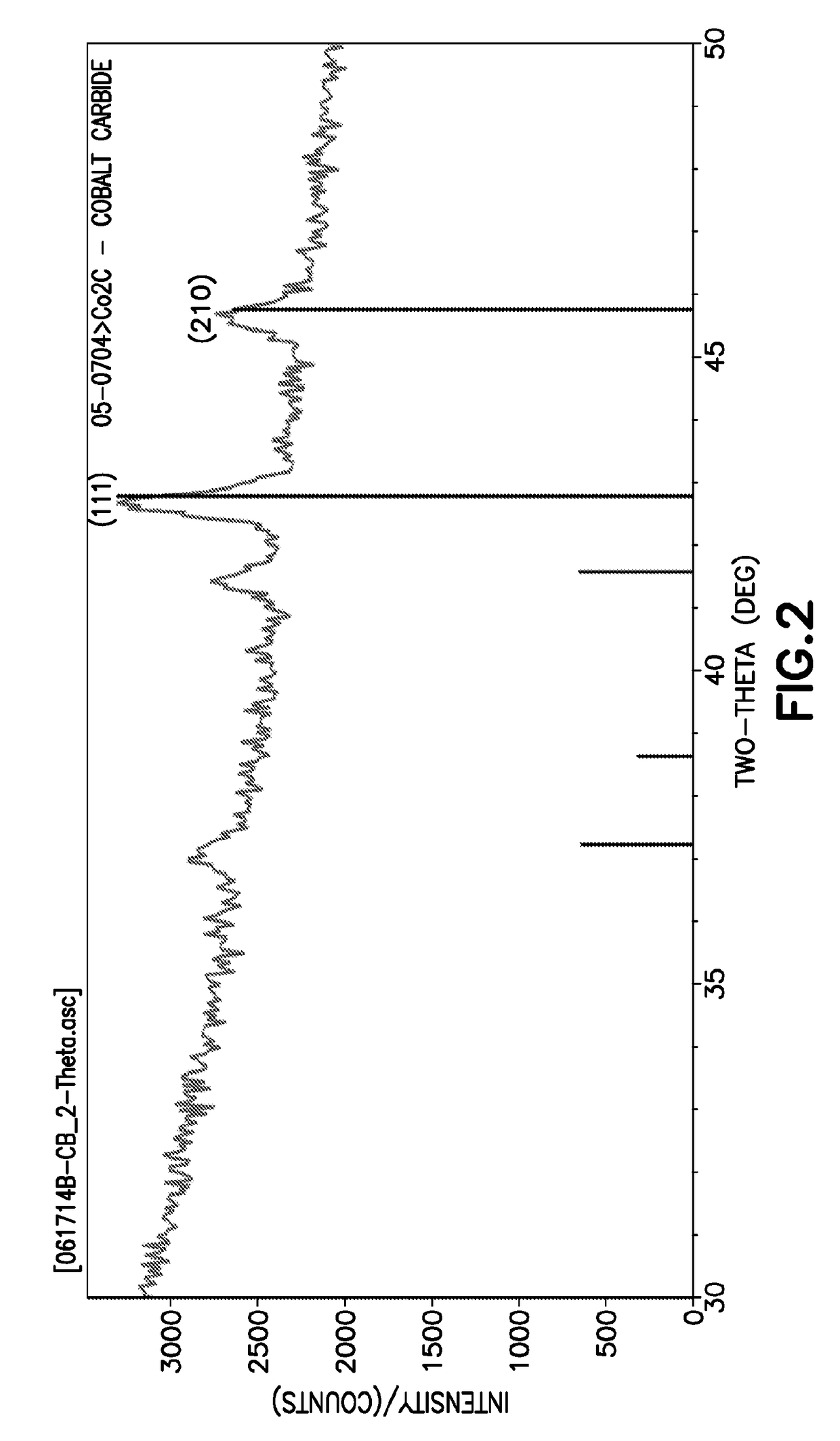
[0119]The Co(tBuNCHCHNtBu)2 precursor then was evaluated in deposition on silicon dioxide substrates, at the following deposition conditions: 290° C. deposition temperature; 50 μmole / minute delivery rate of the precursor, deposition pressure of 10-30 torr; hydrogen as a co-reactant introduced to the deposition chamber at flow rate of 0.5 to 3 L per minute; vaporizer temperature of 130° C.; and 90° C. deposition chamber temperature. The resulting deposited material was in the form of powdery Co2C material. XRD analysis of such deposited Co2C material identified such material has bei...


PUM

PropertyMeasurementUnit
Temperatureaaaaaaaaaa

Abstract

A process for forming cobalt on a substrate, comprising: volatilizing a cobalt precursor of the disclosure, to form, a precursor vapor: and contacting the precursor vapor with the substrate under vapor deposition conditions effective for depositing cobalt on the substrate from the precursor vapor, wherein the vapor deposition conditions include temperature not exceeding 200° C., wherein: the substrate includes copper surface and dielectric material, e.g., ultra-low dielectric material. Such cobalt deposition process can be used to manufacture product articles in which the deposited cobalt forms a capping layer, encapsulating layer, electrode, diffusion layer, or seed for electroplating of metal thereon, e.g., a semiconductor device, flat-panel, display, or solar panel. A cleaning composition containing base and oxidizing agent components may be employed to clean the copper prior to deposition of cobalt thereon, to achieve substantially reduced defects in the deposited cobalt.

Description

CROSS-REFERENCE TO RELATED APPLICATIONS[0001]The benefit of priority under 35 U.S.C. §119 of U.S. Provisional Patent Application No. 62 / 050,166 filed Sep. 14, 2014, U.S. Provisional Patent Application No. 62 / 107,273 filed Jan. 23, 2015, and U.S. Provisional Patent Application No. 62 / 110,078 filed Jan. 30, 2015 is hereby claimed. The disclosures of such U.S. provisional patent applications are hereby incorporated herein by reference, in their respective entireties, for all purposes.FIELD[0002]The present disclosure relates to cobalt precursors for precursors and processes for forming cobalt on substrates, e.g., in the manufacture of semiconductor products, flat-panel displays, and solar panels.DESCRIPTION OF THE RELATED ART[0003]Cobalt is finding increasing use in semiconductor manufacturing, such as in fabrication of integrated circuits in which cobalt disilicide has been progressively displacing titanium silicide as feature and linewidth dimensions decrease, since it does not entai...

Claims


Application Information

Patent Timeline
IPC IPC(8): H01L21/768H01L23/532H01L21/285C23C16/02C23C16/56C23C16/455C23C16/06H01L21/02
CPCH01L21/76879H01L21/02063H01L21/76849H01L21/76864H01L21/76873C23C16/0227H01L23/53238C23C16/45559C23C16/45525C23C16/06C23C16/56H01L21/28562C23C16/02C23C16/04C23C16/18H01L23/53266H01L21/76814H01L21/31144H01L21/32134C23C16/4481
Inventor CHEN, PHILIP S.H.HUNKS, WILLIAMLIPPY, STEVENLIETEN, RUBEN REMCO
Owner ENTEGRIS INC
Learn More