Coal-derived solid hydrocarbon particles

a solid hydrocarbon and coal technology, applied in the field of coal-derived solid hydrocarbon particles, can solve the problems of increasing the cost of coal processing, increasing the cost of processing, and no current commercial process to recover and sell particles, so as to reduce particle agglomeration and inhibit the oxidation of the carbonaceous matter matrix

Active Publication Date: 2018-05-17
EARTH TECH USA
View PDF4 Cites 11 Cited by
  • Summary
  • Abstract
  • Description
  • Claims
  • Application Information

AI Technical Summary

Benefits of technology

[0022]A dispersant is preferably added to the mixture to reduce particle agglomeration and enable subsequent froth flotation, if desired. In one non-limiting embodiment, the dispersant is an organic acid. The dispersant may be an organic acid selected from linear, cyclic, saturated, or unsaturated carboxylic acid and polycarboxylic acids. In one currently preferred embodiment, the dispersant is citric acid. The dispersant preferably inhibits oxidation of the carbonaceous matter matrix of the coal-derived composite particles.

Problems solved by technology

The current industrial process to recover coal particles less than 1 mm in size is more expensive than other coal processing.
The smaller the particles, the greater the processing cost.
Further, there are no current commercial processes to recover and sell particles less than 100 microns (0.1 mm).
While coal fines are the same chemical composition of the larger-size mined coal product, it is considered waste because the conventional coal recovery process is not designed to handle small particles.
The waste coal fines are left unused because they are typically too wet to burn, too dirty to be worth drying, and too fine to transport.
They are often impounded as environmentally hazardous.
Of particular challenge in the coal industry is the burning of coal with typical ash-forming mineral matter components.
The components are the major source of most harmful emissions, such as SOx, and reduce energy value and heat transfer efficiency.

Method used


Image

  • Coal-derived solid hydrocarbon particles
  • Coal-derived solid hydrocarbon particles
  • Coal-derived solid hydrocarbon particles

Examples


example 1

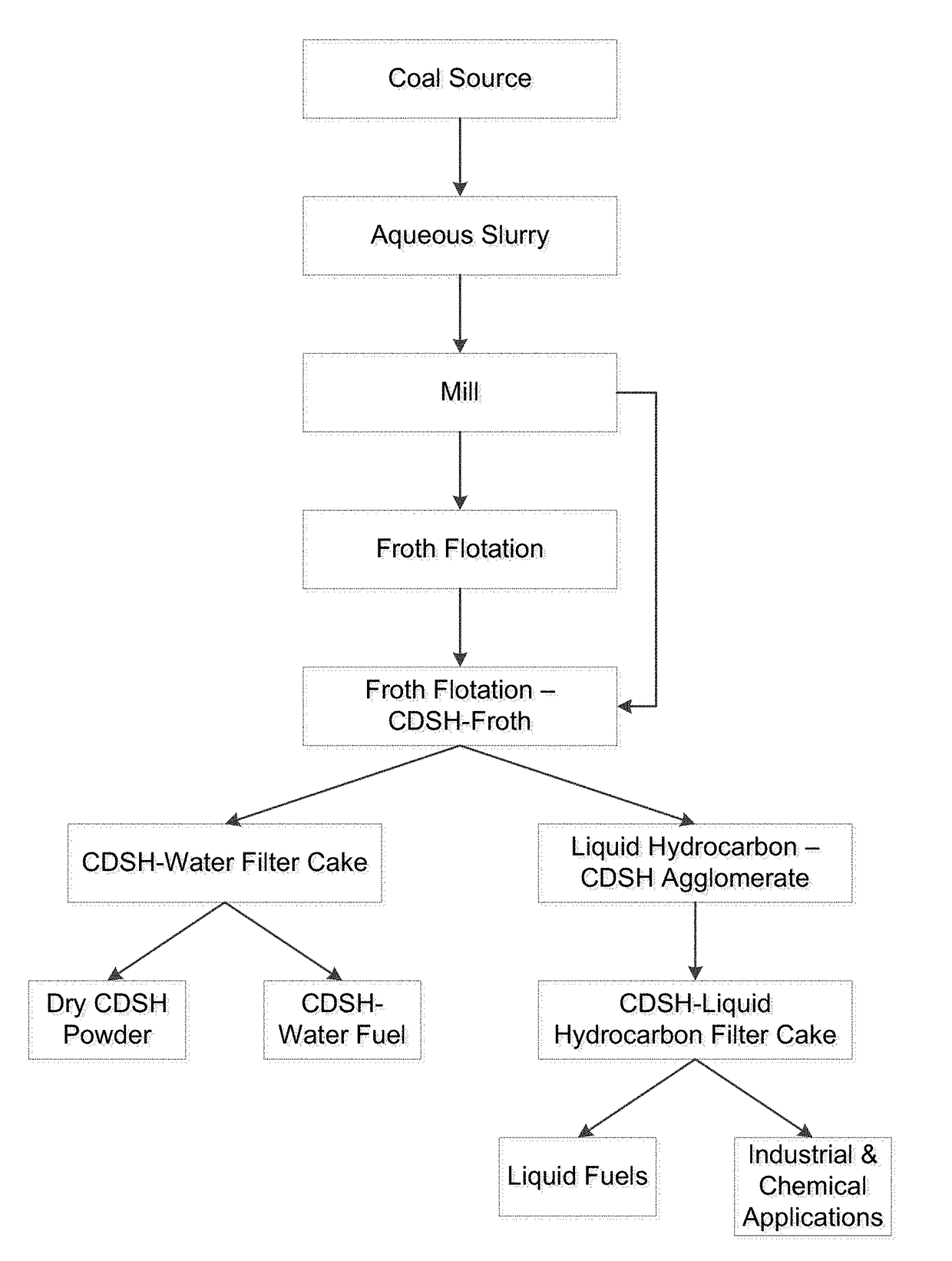
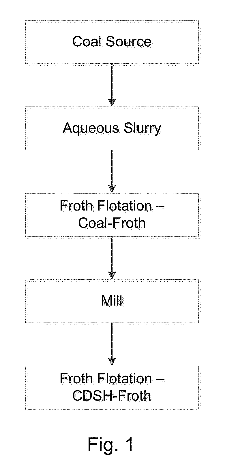
[0059]As illustrated in FIG. 1, an aqueous slurry of coal-derived solids, which may originate from any coal source, was obtained. The aqueous slurry comprised discrete particles of composite coal composed of a solid carbonaceous matter matrix and inherent mineral matter in the carbonaceous matter matrix, discrete particles of coal-derived mineral matter, and a quantity of water. The slurry containing approximately fifty weight percentage (wt. %) solid particles was introduced into a high shear mixer.

[0060]The slurry was then discharged over a 300 micrometer (μm) screen on an orbital sieve. The underflow from the 300 μm screen was introduced into a coal-froth flotation cell where particles of composite coal were separated from particles of coal-derived mineral matter by froth flotation separation. Composite coal particles attached to fine bubbles in the water-bubble region, often called the pulp of the flotation cell. The buoyancy force of the bubble lifted the bubble and composite c...

example 2

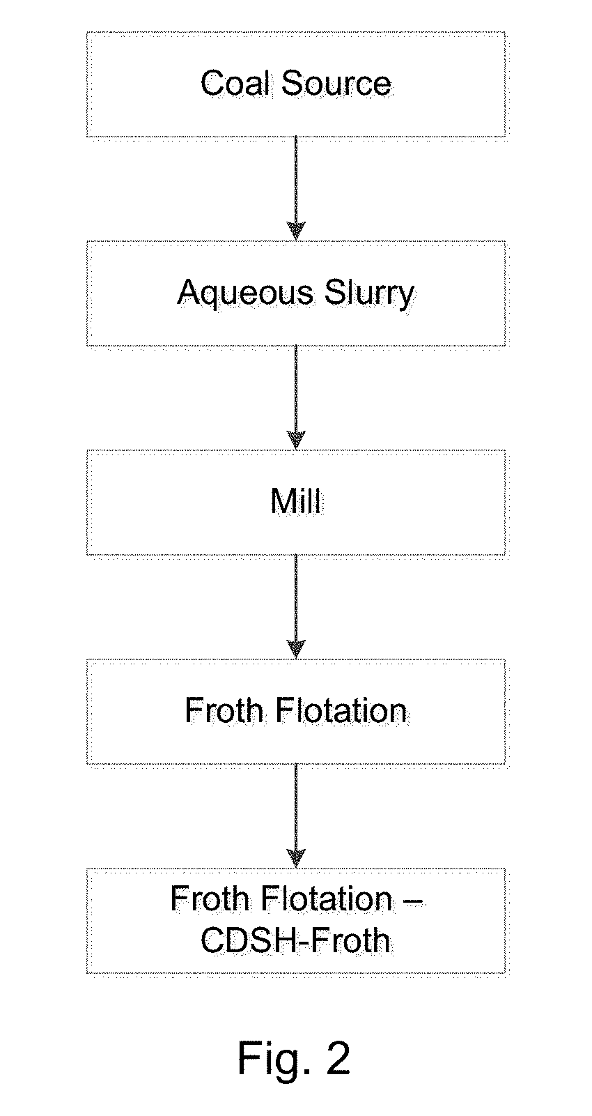
[0065]As an alternative to the process described in Example 1, and as illustrated in FIG. 2, prior to the first froth flotation, the entire aqueous slurry of coal-derived solids, at about 50 wt. % solids, was milled to less than 20 microns with an average particle size between about 2 microns to 4 microns. This milled slurry was then introduced into a froth flotation cell. The froth produced was then floated again in a second flotation step, similar to Example 1. The first flotation removed the bulk of the free coal-derived mineral matter. However, some of the free coal-derived mineral matter was communicated to the first froth in the water. The reason for this is that the source of the water in the froth is the water in the pulp of the flotation cell. The pulp of the flotation cell also contains the hydrophilic coal-derived mineral matter in suspension. As water is included in the froth phase, so is coal-derived mineral matter in that water. The second flotation served to largely r...

example 3

[0069]As an alternative to the process described in Examples 1 and 2, and as illustrated in FIG. 3, prior to the first flotation, the entire aqueous slurry of coal-derived solids was milled to less than 10 microns with an average size of about 2 microns. This milled slurry was then introduced into a froth flotation cell. In this case, the solids content in the pulp was continually diluted to less than 4 wt. % solids to minimize the free coal-derived mineral matter available for entrainment in the froth being produced. The coal-derived mineral matter content of the froth was 1.08 wt. % on a dry basis. Further, counter-current wash water was dripped over the CDSH-froth. The CDSH-froth with counter current wash water contained 0.46 wt. % coal-derived mineral matter particles on a dry basis.

[0070]In this example, coal-derived solid hydrocarbon can be produced by first milling the slurry such that all particles are less than 10 microns with an average size of about 2 micron. By maintaini...


PUM

PropertyMeasurementUnit
particle sizeaaaaaaaaaa

Abstract

The coal-derived solid hydrocarbon particles are discrete particles of coal-derived carbonaceous matter having a particle size less than about 10 μm that are substantially free of inherent or entrained mineral matter. The particles of have an average particle size in the range from 1 μm to 8 μm. The particles of coal-derived carbonaceous matter are milled to a size approximately the same as a size of coal-derived mineral matter inherent in the coal source to release inherent coal-derived mineral matter particles such that the particles of carbonaceous matter and the particles of mineral matter are discrete and separable solid particles. Following separation, less than 1.5 wt. % discrete coal-derived mineral matter particles are associated with the discrete particles of coal-derived carbonaceous matter. Particles of coal-derived solid hydrocarbon matter are blended with a gaseous or liquid hydrocarbon fuel to form a two-phase hydrocarbon fuel feedstock.

Description

CROSS-REFERENCE TO RELATED APPLICATION[0001]This application claims the benefit of U.S. Provisional Application No. 62 / 421,128, filed Nov. 11, 2016, and entitled COAL-DERIVED SOLID HYDROCARBON PARTICLES. This prior application is incorporated by reference.BACKGROUND OF THE INVENTION[0002]This disclosure relates to coal-derived solid hydrocarbon particles and methods of preparing such particles. Coal-derived solid particles include coal-derived carbonaceous matter and coal-derived mineral matter. Coal-derived solid hydrocarbon particles include discrete solid coal-derived carbonaceous matter particles, derived from any coal source, which are milled to a sufficiently small size to be substantially free of inherent or entrained mineral matter. Systems and methods for the separating coal-derived carbonaceous matter particles from coal-derived mineral matter particles are disclosed. The resulting coal-derived solid hydrocarbon particles are substantially free of inherent or entrained coa...

Claims


Application Information

Patent Timeline
Patent Type & Authority Applications(United States)
IPC IPC(8): C10L5/00C10L1/32C10L3/00
CPCC10L5/00C10L1/322C10L1/326C10L3/003C10L10/02C10L10/06C10L2230/22C10L2250/06C10L2290/547C10L2290/24C10L2290/54C10L5/04C10L5/366C10L2290/28B03D1/025B03D2203/08B03D2201/005B03D1/02B03D1/08C10G73/36B03D1/10B03D1/082B01D33/62B07B13/04C10L9/00C10L5/06
Inventor SWENSEN, JAMES S.HODSON, SIMON K.
Owner EARTH TECH USA
Why Eureka
Try Eureka