

Systems and Methods for Controlling Pressure in a Cryogenic Energy Storage System
a technology of cryogenic energy storage and system, applied in the direction of non-pressured vessels, container discharge methods, mechanical equipment, etc., can solve the problems of heat ingress into the insulated tank, affecting the operation of the system, and the method is usually limited, so as to reduce the inefficiency of venting this gas to the atmosphere, and the effect of reducing the build-up of pressur
- Summary
- Abstract
- Description
- Claims
- Application Information
AI Technical Summary
Benefits of technology
Problems solved by technology
Method used
Image

Examples
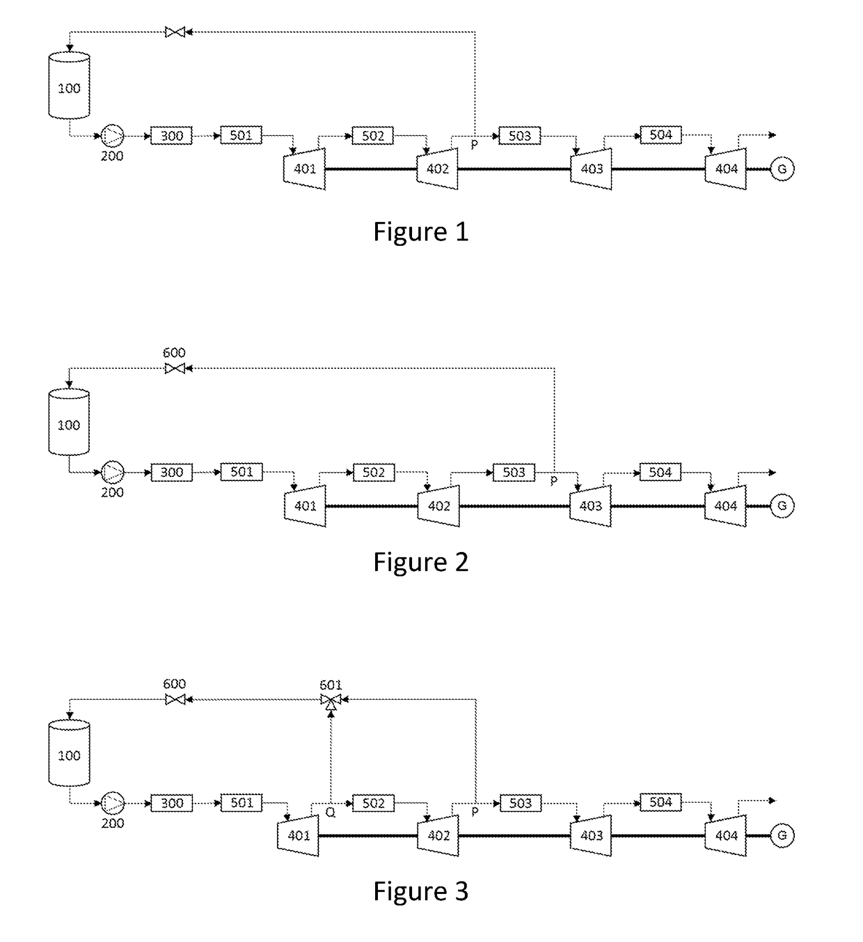
first embodiment
[0173]the invention is shown in FIG. 1, which illustrates a power recovery unit of a LAES system. According to this embodiment, cryogenic liquid is stored in cryogenic storage tank 100 with a pressure of approximately 8 bar in the headspace of the tank.
[0174]During a first power recovery period cryogenic liquid stored in cryogenic storage tank 100 is withdrawn from the bottom of tank 100 at a rate of 100 kg / s and pumped to a pressure of 100 bar in cryogenic pump 200. The resulting high-pressure cryogenic liquid is then substantially vaporised in evaporator 300, emerging as a gaseous stream, at a temperature of approximately 15° C. Said gaseous stream is then further heated in first heating device 501 to a temperature of 80° C. before being expanded in first expansion stage 401 to a pressure of approximately 32 bar. The gaseous stream is now at a temperature of approximately 0° C. and is reheated in second heating device 502 to 80° C. before entering second expansion stage 402. The g...
third embodiment
[0191]The advantage of this third embodiment is that if the pressure at point P falls below the pressure in the headspace of tank 100 due to a reduction in the power output of the system, connection point Q, which is at a higher pressure, may be selected instead. Suitable sensing and control means may be provided to achieve this, as a skilled person would appreciate. In circumstances in which the pressure at connection point P is sufficient, however, this connection point may be selected such that further work may be extracted from the gaseous stream before a portion is diverted to the pressurisation stream.
[0192]As is common practice in the safe design of all cryogenic energy storage systems, the pressure in the tank of all the above embodiments may be prevented from rising above design value by means of a pressure relief valve (not shown).
[0193]A person skilled in the art will understand that the above-described embodiments are purely exemplary arrangements that depict implementat...
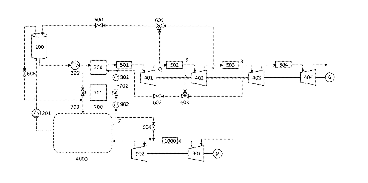
tenth embodiment
[0209]The advantage of this tenth embodiment is that if the pressures at points P or R fall below the pressure in the headspace of tank 100 or the pressure of cold recycle system 700 respectively, due to a reduction in the power output of the system, connection points Q or S respectively, which are at a higher pressure respectively, may be selected instead.
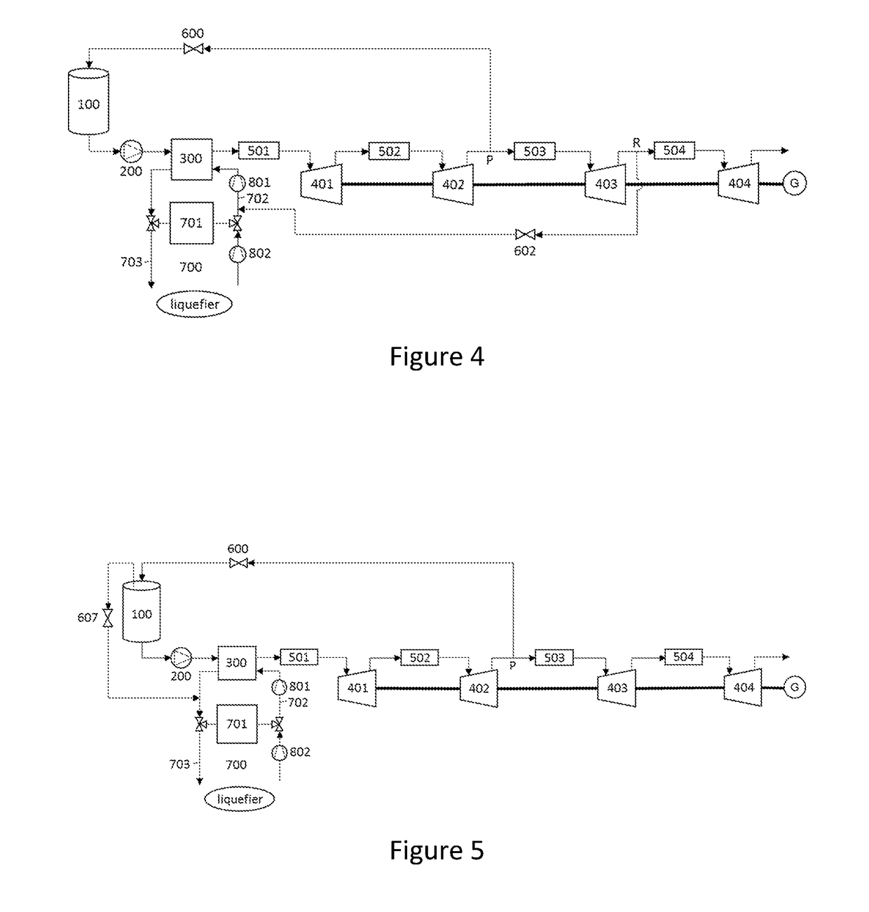
[0210]It should be understood that the described embodiments are just exemplary arrangements of the invention. The same invention may be implemented using any combination of connections, including: between the cryogenic tank and the liquefaction system; between the cold recycle system and the liquefaction system; and between the cryogenic tank and the cold recycle system (with or without a subsequent connection between the cold recycle system and the liquefaction system). There may also be provided a connection between the cryogenic tank and the cold recycle system upstream of the cold store; and / or a connection between the cryoge...
PUM
 Abstract
Description
Claims
Application Information