
Variable focal length lens system with multi-level extended depth of field image processing

a variable focal length and depth of field technology, applied in the field of precision metrology using variable focus lenses, can solve the problems of relatively slow method, mechanical complexity, and relatively slow method, and achieve the effects of less image processing, less defocus blur, and less image processing

Active Publication Date: 2018-05-24
MITUTOYO CORP
View PDF0 Cites 19 Cited by
  • Summary
  • Abstract
  • Description
  • Claims
  • Application Information

AI Technical Summary

Benefits of technology

The patent describes a system and method for displaying a live extended depth of field image of a moving workpiece. The system includes a lens system, control system, and camera that can capture images of the workpiece at different focus distances, resulting in a raw extended depth of field image data. An image processing portion then processes the raw data to provide a high-quality extended depth of field image that removes defocus blur. The system can also update the live extended depth of field image based on the translation speed of the workpiece, displaying different types of images depending on the speed. The technical effects of this system include improved quality and clarity of extended depth of field images and improved tracking of moving workpieces.

Problems solved by technology

However, this method is relatively slow.
However, such a method is relatively slow and mechanically complex, which can cause issues for certain types of applications (e.g., when displaying a live EDOF image of a workpiece that is being moved across a field of view, for which the processing may be too slow to keep up with the motion, etc.) An improved method for providing EDOF images (e.g., such as may be performed when providing live EDOF images, etc.) is desirable.

Method used


Image

  • Variable focal length lens system with multi-level extended depth of field image processing
  • Variable focal length lens system with multi-level extended depth of field image processing
  • Variable focal length lens system with multi-level extended depth of field image processing

Examples


Embodiment Construction

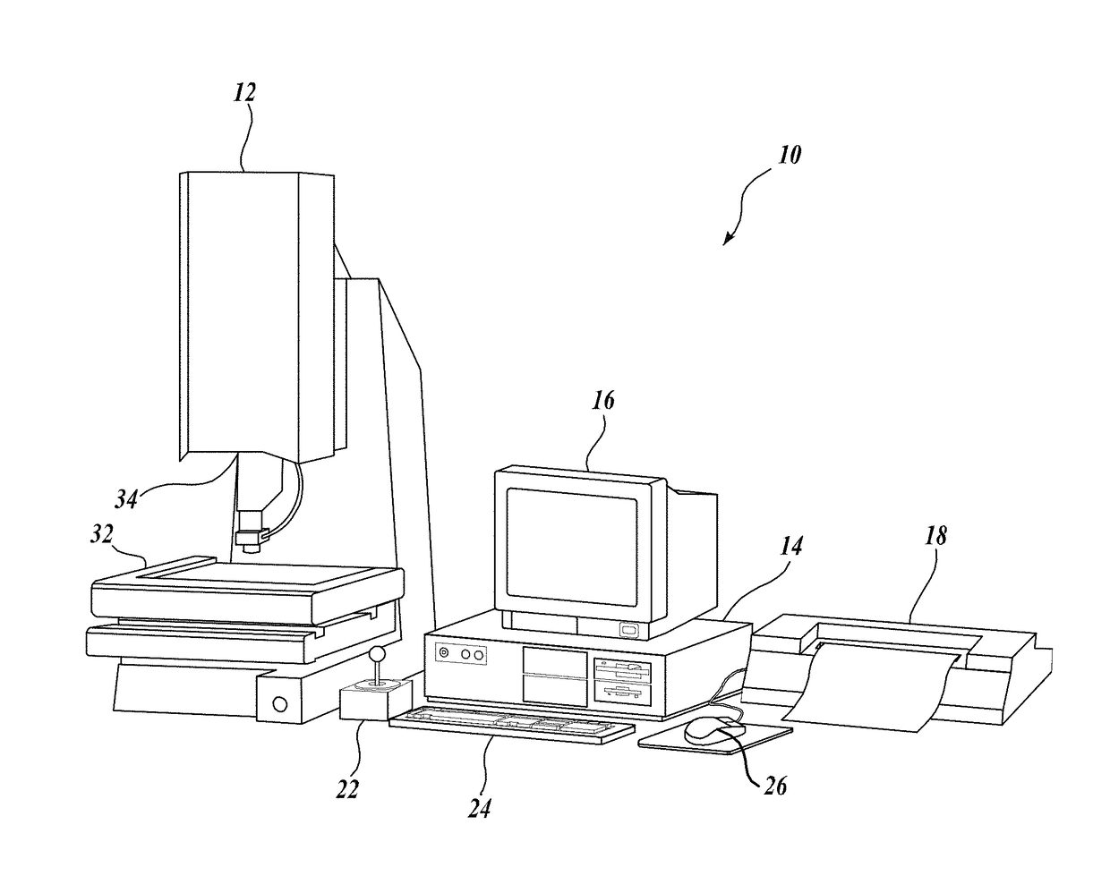
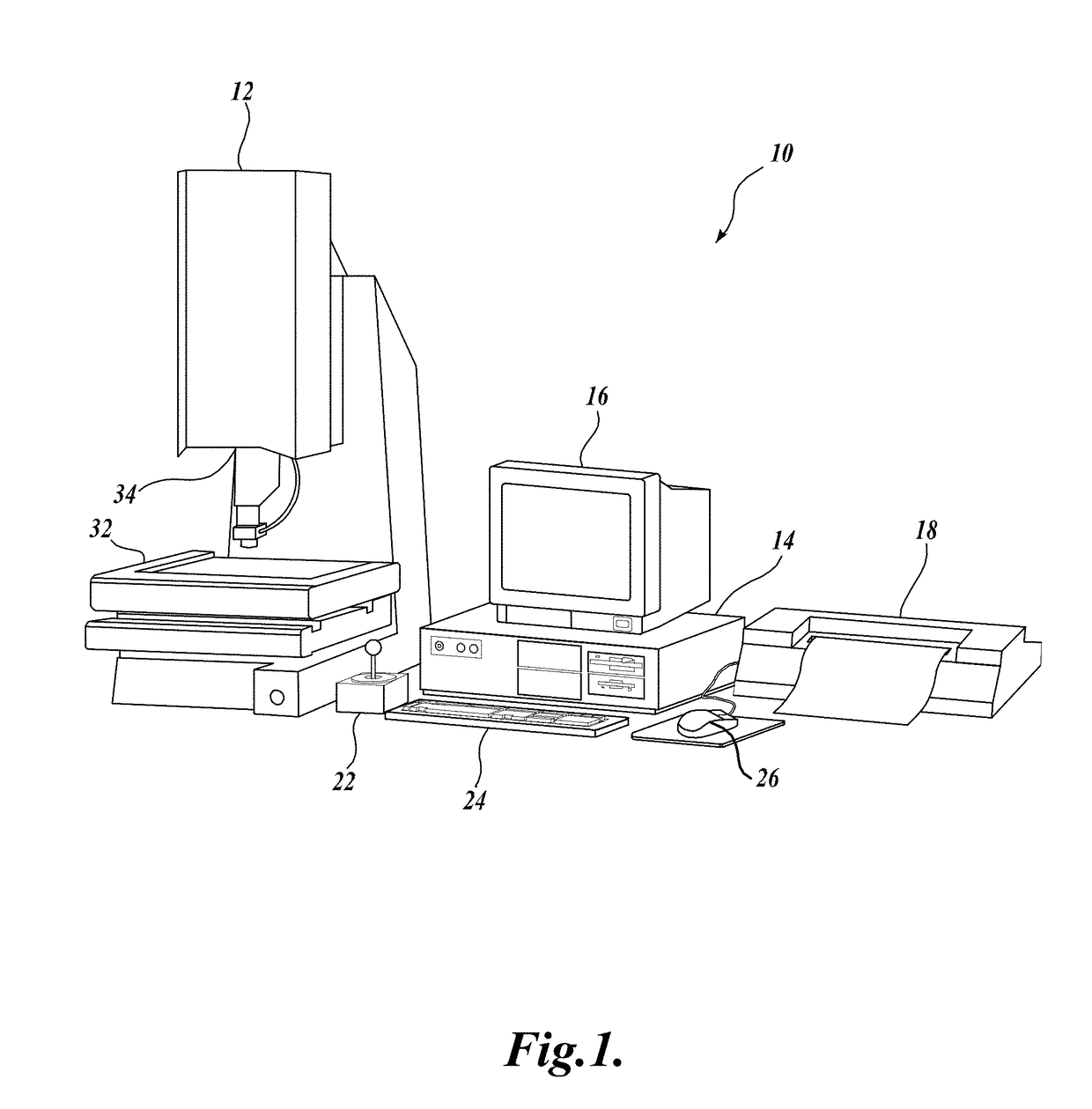
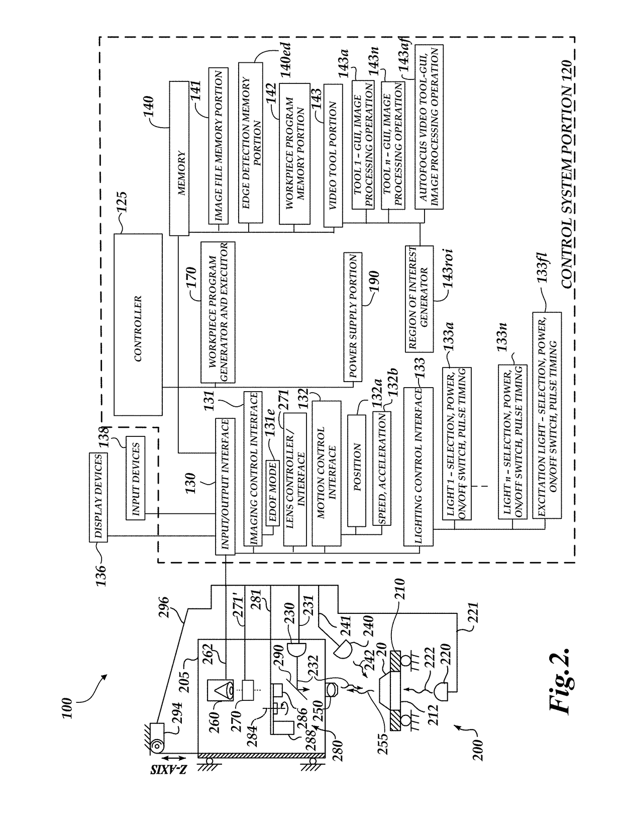
[0018]FIG. 1 is a block diagram of one exemplary machine vision inspection system 10 which includes an imaging system usable in accordance with principles disclosed herein. The vision system 10 includes a vision measuring machine 12 operably connected to exchange data and control signals with a controlling computer system 14, a monitor or display 16, a printer 18, a joystick 22, a keyboard 24, and a mouse 26. The monitor or display 16 may display a user interface for controlling and / or programming the vision system 10. A touchscreen tablet or the like may be substituted for or augment any or all of these components.

[0019]More generally, the controlling computer system 14 may comprise or consist of any computing system or device, and / or distributed computing environment, and may include one or more processors that execute software to perform the functions described herein. Processors include programmable general- or special-purpose microprocessors, controllers, application-specific i...


PUM

PropertyMeasurementUnit
frequencyaaaaaaaaaa
depth of fieldaaaaaaaaaa
focus distancesaaaaaaaaaa

Abstract

An imaging system including a tunable acoustic gradient (TAG) lens is associated with a user interface including a live display of an extended depth of field (EDOF) image. The TAG lens is utilized to produce a raw EDOF image, which may include defocus blur (e.g., resulting in part from the periodically modulated optical power variation of the TAG lens). The live EDOF image is repetitively updated in the user interface based on a translation state signal at a current time (e.g., indicating a speed of translation of the workpiece across a field of view of the imaging system, etc.) In response to a current state of the translation state signal, a corresponding type of live EDOF image of the workpiece is displayed in the user interface corresponding to an EDOF image data set that is based on a corresponding level of image processing to remove defocus blur.

Description

BACKGROUNDTechnical Field[0001]This disclosure relates generally to precision metrology using a variable focus lens, and more particularly to extended depth-of-field imaging operations such as may be utilized in machine vision inspection or other vision systems.Description of the Related Art[0002]Precision machine vision inspection systems (or “vision systems” for short) are used to obtain precise dimensional measurements of objects and to inspect various other object characteristics. Such systems may include a computer, a camera and optical system, and a precision stage that moves to allow workpiece traversal and inspection. One exemplary prior art system, characterized as a general-purpose “off-line” precision vision system, is the QUICK VISION® series of PC-based vision systems and QVPAK® software available from Mitutoyo America Corporation (MAC), located in Aurora, Ill. The features and operation of the QUICK VISION® series of vision systems and the QVPAK® software are generally...

Claims


Application Information

Patent Timeline
Patent Type & Authority Applications(United States)
IPC IPC(8): G02B21/36G06T5/00H04N5/232G02F1/11G02B21/00
CPCG02B21/367G06T5/003G02B21/0016H04N5/23216G02F1/113H04N5/23212G01C11/02G01C11/04H04N23/67G06T5/50G06T2200/21G06T2207/10052H04N23/676H04N23/62H04N23/951G06T5/73
Inventor BRYLL, ROBERT KAMILNAGAHAMA, TATSUYA
Owner MITUTOYO CORP
Learn More