Amplification optical fiber and laser device

Active Publication Date: 2018-07-19
THE FUJIKURA CABLE WORKS LTD
View PDF20 Cites 3 Cited by
  • Summary
  • Abstract
  • Description
  • Claims
  • Application Information

AI Technical Summary

Benefits of technology

The patent describes an amplification optical fiber that can suppress nonlinear optical effects such as stimulated Raman scattering even in high-power laser devices. The fiber has a large diameter core and inner cladding with a higher refractive index than the outer cladding, allowing for easy pumping and amplification of light. The twist applied to the inner cladding facilitates repeated reflection of pumping light, suppressing mode coupling. The fiber also prevents mode coupling and reduces transmission loss by preventing the active element from crystallizing. The fiber emits laser light with a high proportion of the fundamental mode, preventing mode coupling and maintaining beam quality. Overall, the patent describes a technical solution for improving the performance of amplification optical fibers.

Problems solved by technology

If, however, the power of light propagating through an optical fiber is increased, nonlinear optical effects such as stimulated Raman scattering become likely to occur in the optical fiber.
Since, however, multi-mode light propagates through a core in an LMA fiber, the beam quality may be degraded by mode coupling.
As a result, the refractive index of the core fluctuates unevenly, which will make mode coupling of light propagating through the core more likely to occur.

Method used


Image

  • Amplification optical fiber and laser device
  • Amplification optical fiber and laser device
  • Amplification optical fiber and laser device

Examples


first embodiment

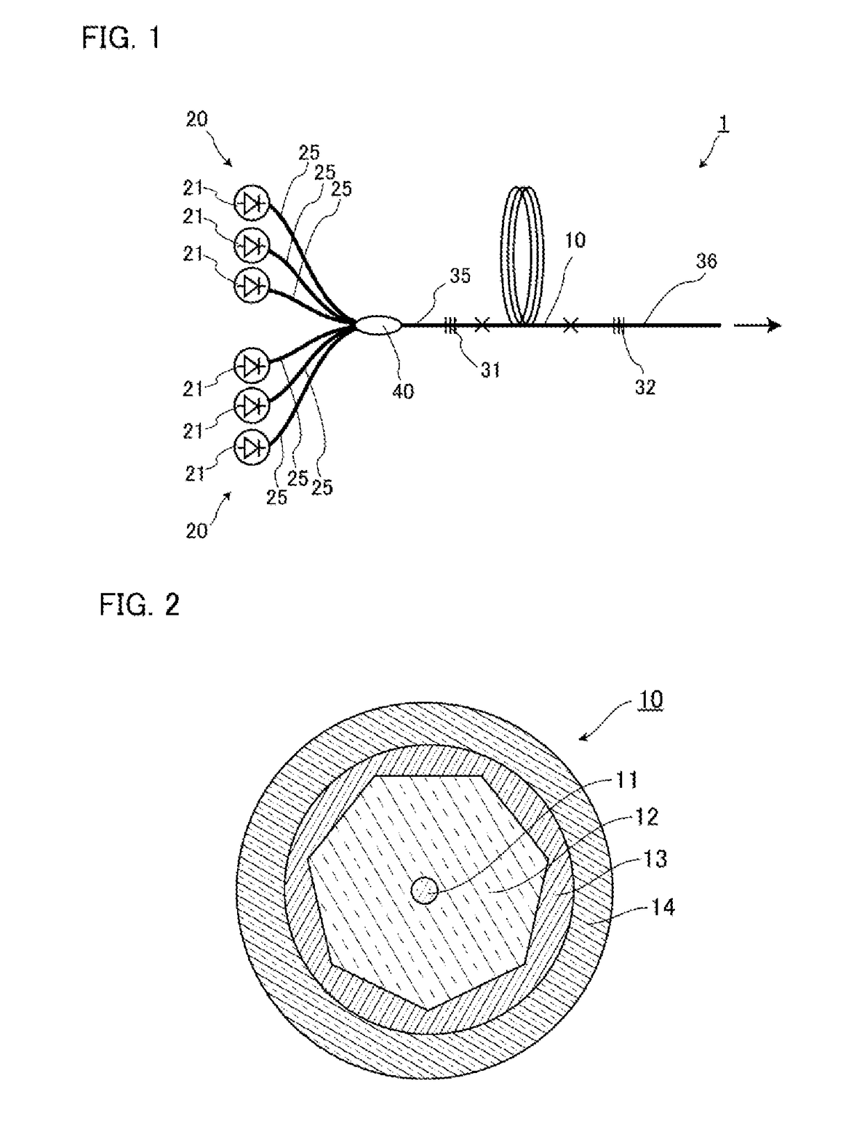
[0029]FIG. 1 is a diagram describing a laser device according to a first embodiment of the present invention. As illustrated in FIG. 1, a laser device 1 of the present embodiment includes, as main components, an amplification optical fiber 10, a pumping light source 20, an optical combiner 40, an optical fiber 35 connected to one end of the amplification optical fiber 10, a first FBG 31 provided in the optical fiber 35, an optical fiber 36 connected to the other end of the amplification optical fiber 10, and a second FBG 32 provided in the optical fiber 36, in which the amplification optical fiber 10, the first FBG 31, and the second FBG 32 constitutes a cavity.

[0030]The pumping light source 20 is constituted by a plurality of laser diodes 21, which are Fabry-Perot semiconductor lasers of a GaAs semiconductor material and emit pumping light having a center wavelength of 915 nm in the present embodiment, for example. Each of the laser diodes 21 of the pumping light source 20 is conne...

second embodiment

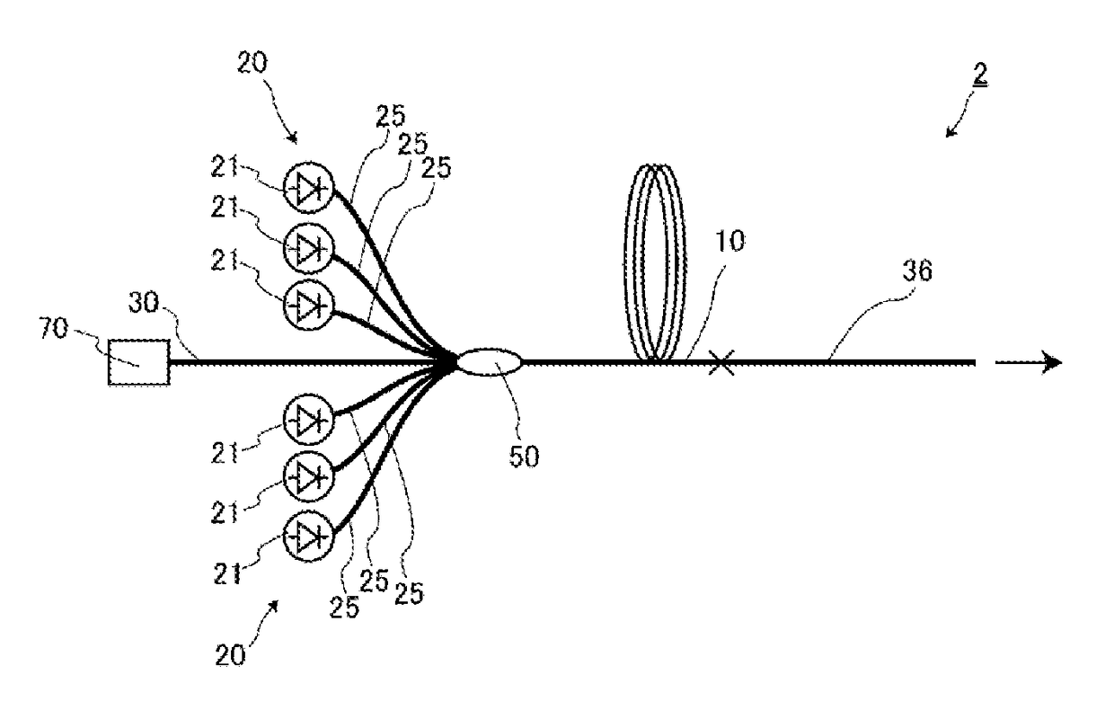
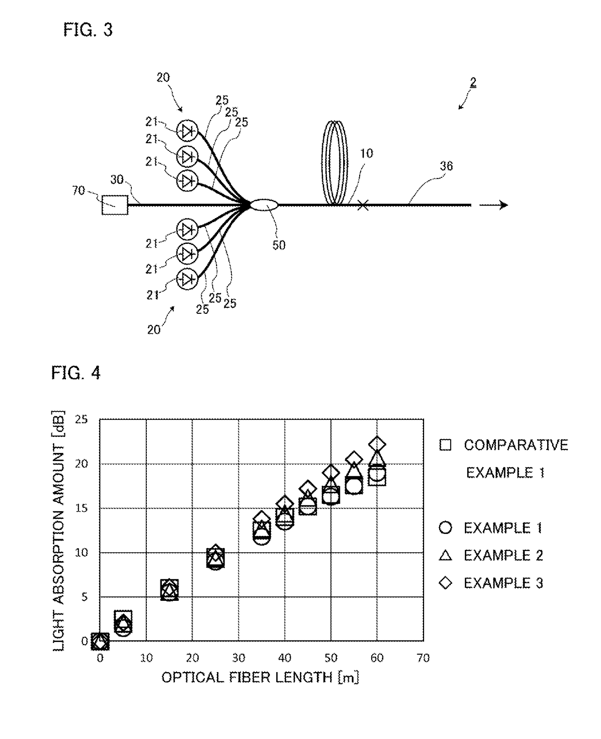
[0048]Next, a second embodiment of the present invention will be described in detail with reference to FIG. 3. Note that components that are identical or equivalent to those in the first embodiment may be designated by the same reference numerals and redundant description may not be repeated unless otherwise particularly described.

[0049]FIG. 3 is a diagram illustrating a laser device according to the present embodiment. As illustrated in FIG. 3, a laser device 2 of the present embodiment is different from the laser device 1 of the first embodiment in that the laser device 2 is a master oscillator power amplifier (MO-PA) fiber laser device. Thus, the laser device 2 of the present embodiment includes a seed light source 70, and an optical fiber 30 connected with the seed light source 70.

[0050]The seed light source 70 is constituted by a laser diode, a fiber laser, or the like, for example. The optical fiber 30 includes, as main components, a core doped with no active element, cladding...

example 1

[0055]An optical fiber corresponding to the amplification optical fiber 10 was produced in the following method. First, an optical fiber preform made of glass having the same refractive index profile as the core 11 and the inner cladding 12 of the amplification optical fiber 10 was provided. Specifically, an optical fiber preform in which the outer surface of a columnar material to be the core 11 is surrounded by a material of a heptagonal prism to be the inner cladding 12 without any gap therebetween was provided. Subsequently, the optical fiber preform was suspended in such a manner that the longitudinal direction of the optical fiber preform is vertical. The optical fiber preform was then placed in a drawing furnace, and a bottom end part of the optical fiber preform was heated. Subsequently, glass melted from the bottom end part of the heated optical fiber preform was drawn from the drawing furnace at a predetermined drawing rate and cooled. In this process, drawing was performe...


PUM


Abstract

An amplification optical fiber according to the present invention includes: a core doped with an active element, through which multi-mode light propagates; an inner cladding that surrounds the core and has a refractive index lower than that of the core; and an outer cladding that surrounds the inner cladding and has a refractive index lower than that of the inner cladding. The inner cladding has a polygonal outline in a cross section perpendicular to the longitudinal direction, and the inner cladding has a permanent twist applied by turning around the central axis of the core.

Description

TECHNICAL FIELD[0001]The present invention relates to an amplification optical fiber and a laser device capable of suppressing occurrence of a skew mode while suppressing mode coupling.BACKGROUND ART[0002]Fiber laser devices are excellent in focusing performance, produce a small beam spot of light having high power density, and are therefore used in various fields such as the laser processing field and the medical field. In such a fiber laser device, a rare earth-doped fiber having a core doped with a rare earth element is used. Typically, a double-clad structure is applied to a rare earth-doped fiber so that more pumping light enter the core. A rare earth-doped fiber having a double-clad structure includes a core doped with a rare earth element, inner cladding surrounding the core, and outer cladding surrounding the inner cladding and having a refractive index lower than that of the inner cladding. Pumping light having entered the inner cladding is reflected by an interface between...

Claims


Application Information

Patent Timeline
IPC IPC(8): G02B6/036H01S3/067H01S3/10
CPCG02B6/03616H01S3/067G02B6/03605H01S3/10007G02B6/03694H01S3/06729H01S3/06733H01S3/0675H01S2301/03H01S3/08045H01S3/06754G02B6/03633G02B6/02047
Inventor KITAHARA, RINTARO
Owner THE FUJIKURA CABLE WORKS LTD
Why Eureka
Try Eureka