Supercharge Your Innovation With Domain-Expert AI Agents!

Method of manufacturing shadow mask using hybrid processing and shadow mask manufactured thereby

a technology of hybrid processing and manufacturing method, which is applied in the field of manufacturing method of metal shadow mask and metal shadow mask, and the manufacture of shadow mask thereby, can solve the problems of performance degradation of display device, affecting the precision the aperture peripheries may have a bad effect on precisely and stably securing aperture size or shape, etc., to achieve the effect of improving the performance of display device and high quality

Active Publication Date: 2018-07-19
APS HLDG CORP
View PDF3 Cites 0 Cited by
  • Summary
  • Abstract
  • Description
  • Claims
  • Application Information

AI Technical Summary

Benefits of technology

The present invention solves the productivity degradation of conventional laser processing by using hybrid processing including wet etching and laser processing to manufacture a high-quality shadow mask. This method prevents the isotropic characteristic of wet etching and improves the performance of display devices by preventing the gradual deposition of electro luminescence material and allowing for the formation of various shapes of apertures. The shadow mask of the present invention may be used for display devices having resolutions of QHD or UDH.

Problems solved by technology

Thus, the thinness of peripheries of the aperture may have a bad effect on precisely and stably securing a size or shape of the aperture.
When depositing the electroluminescence material through the aperture of the metal mask, the electroluminescence material is not uniformly deposited on the substrate due to the undercut shape.
As a result, a performance degradation of the display device occurs when manufacturing by using such a metal mask.
However, it is difficult to use conventional wet etching methods to produce display devices having resolutions of QHD (approximately 500 ppi) or UHD (approximately 800 ppi).
However, the value of PR width A cannot become an infinitely small value because it is difficult to obtain a very small value of PR width A due to the characteristic of an exposure process.
Although an infinitely small value is obtained, it may cause degradation of an etching factor.
This is because, although the method of etching both sides of the metal mask is used, referring to FIG. 3, the size of the undercut becomes larger when the depth D value becomes smaller, thus the electroluminescence material is not uniformly deposited on the substrate.
Further, a thickness T of the metal mask cannot be decreased since there is a minimal thickness required to handle the metal sheet during wet etching.
In addition, it is also difficult to implement display devices with high resolutions by only performing wet etching.
Such characteristics are characteristics that are difficult to be applied in display devices that require sharp quadrangular or polygonal deposition areas.
In particular, it is difficult for such characteristics to be applied in display devices with high resolutions such as QHD or UHD.
Therefore, it is difficult to implement display devices having resolutions of QHD (approximately 500 ppi) or UHD (approximately 800 ppi) by using conventional wet etching due to limits and correlations between factors of the shape described above.
In addition, there is a limit to implement a wet-etched pattern that has a certain radius of curvature of a wet-etched surface by using conventional wet etching due to the isotropic characteristic thereof, and thus, it is difficult to implement apertures having various shapes.
However, the biggest limitation of the above method is that it is difficult to ensure productivity capable of being used in industrial sites.
However, heat due to the high energy applied to the metal base cannot be sufficiently dissipated and is accumulated on the metal base, thus the accumulated heat causes degradation of processing quality.
However, it is difficult to ensure sufficient productivity by using such method.

Method used


Image

  • Method of manufacturing shadow mask using hybrid processing and shadow mask manufactured thereby
  • Method of manufacturing shadow mask using hybrid processing and shadow mask manufactured thereby
  • Method of manufacturing shadow mask using hybrid processing and shadow mask manufactured thereby

Examples


Embodiment Construction

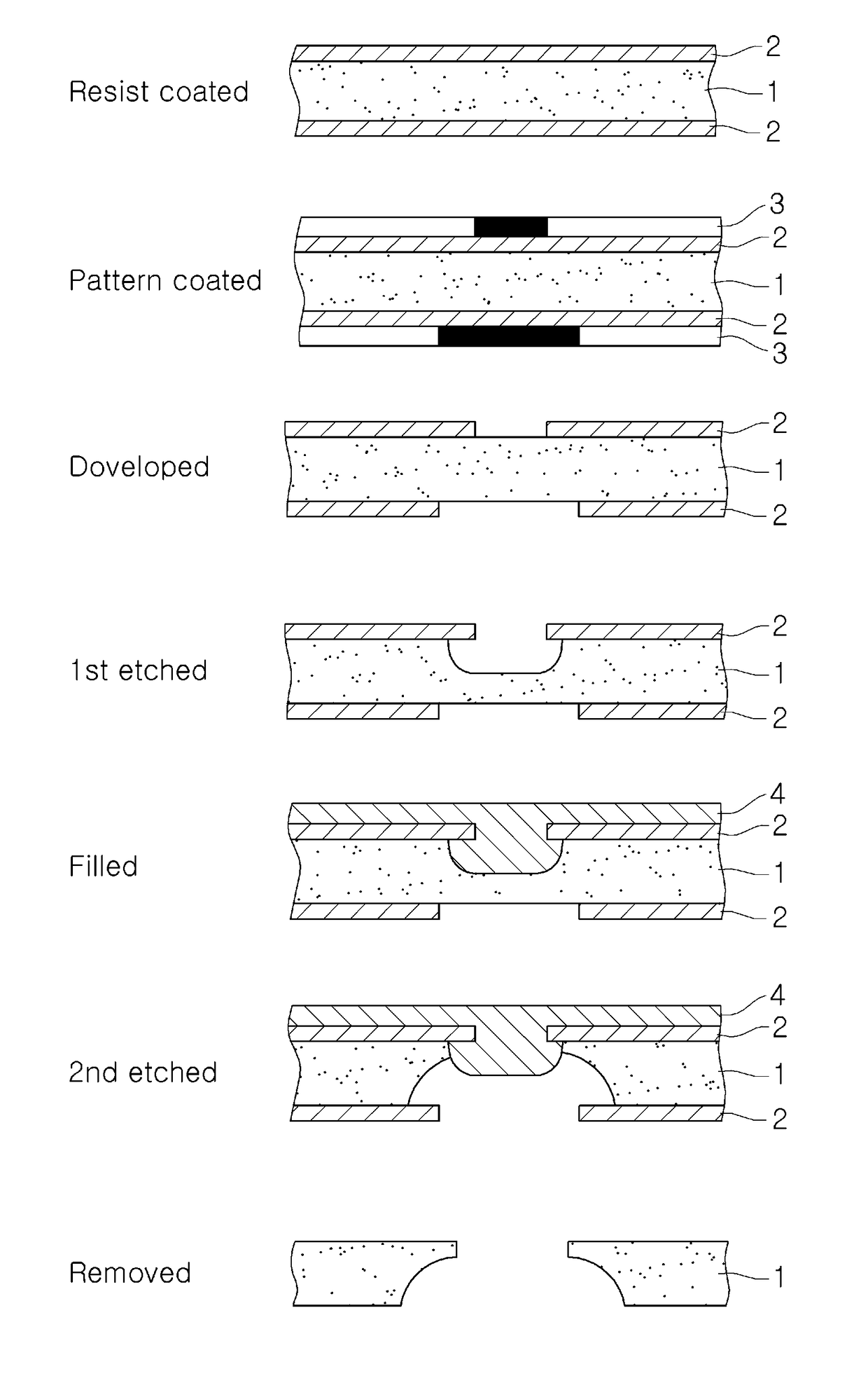
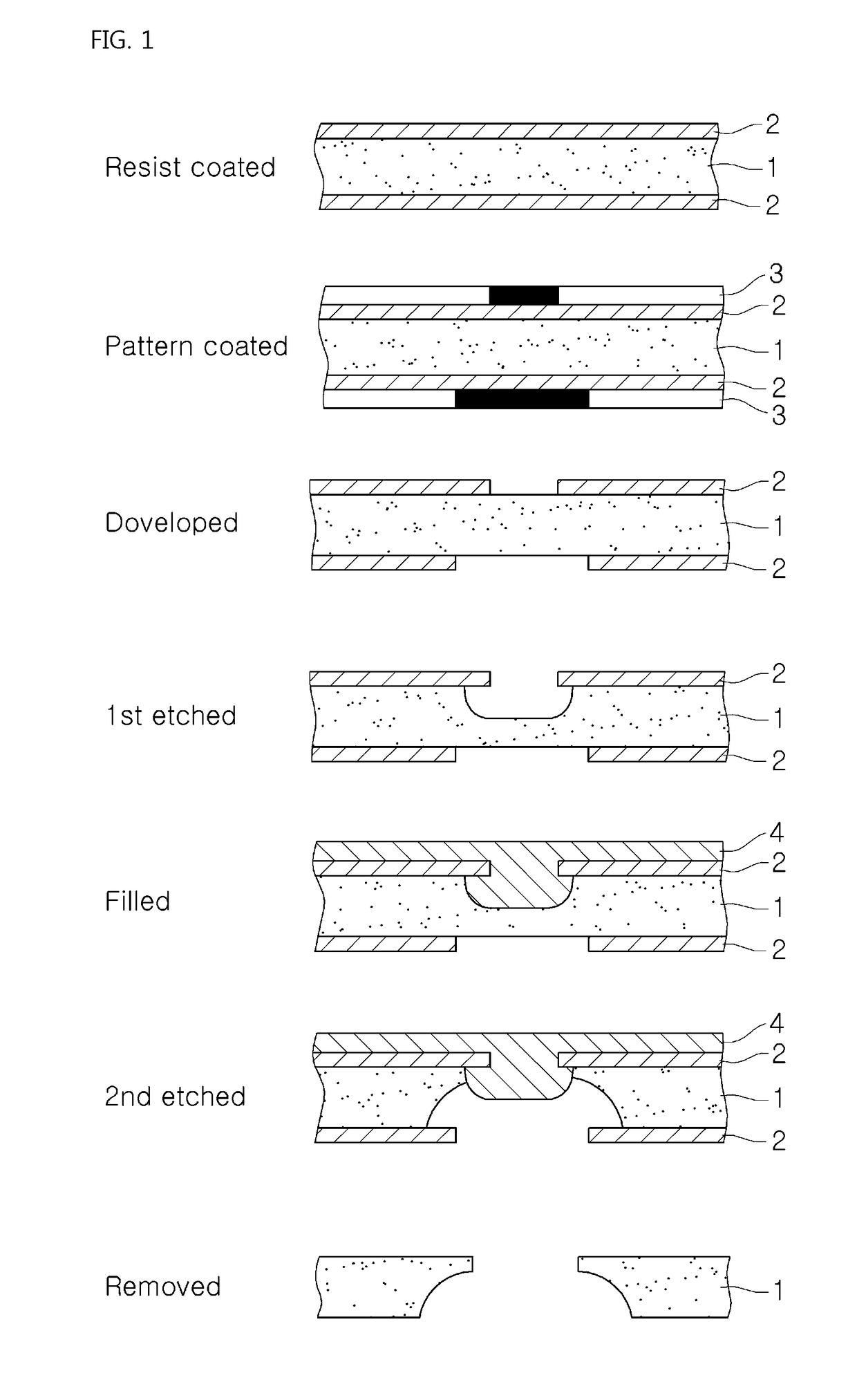
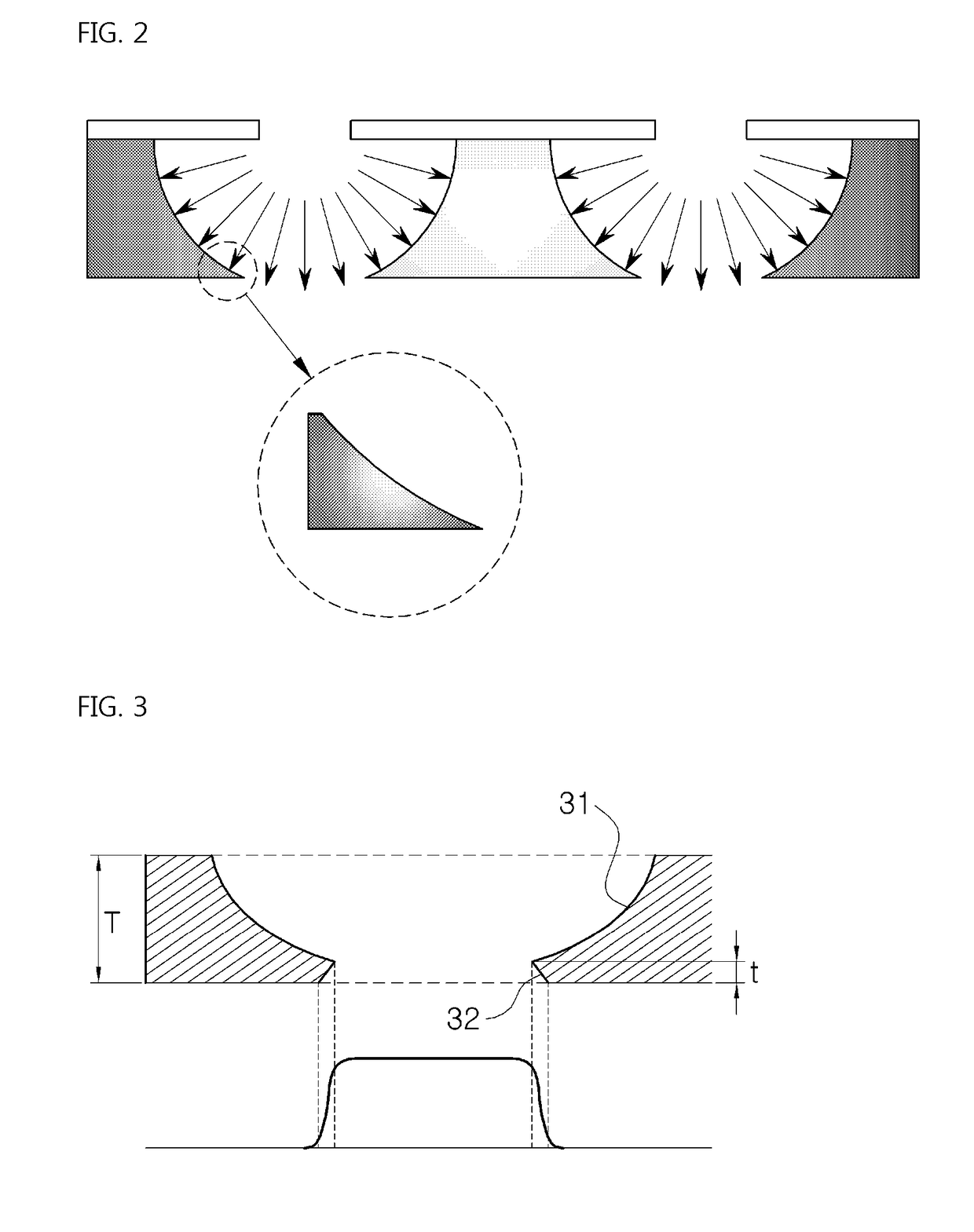
[0074]The present invention generally relates to a method of manufacturing a metal shadow mask used for a deposition process while manufacturing an organic EL devices or an organic semiconductor. More particularly, the present invention relates to a method of manufacturing a metal shadow mask, wherein hybrid processing including wet etching and laser processing are used to form a mask pattern having a laser-processed pattern and a wet-etched pattern on the shadow mask.

[0075]Thus, productivity degradation of conventional laser processing may be solved, and a shadow mask with high quality is provided by performing wet etching.

[0076]Hereinafter, exemplary embodiments of the present invention will be described in detail with reference to the accompanying drawings. FIG. 8 is a schematic view of a method of manufacturing a shadow mask according to an embodiment of the present invention, FIG. 9 is a schematic view of a method of manufacturing a shadow mask according to another embodiment o...


PUM

PropertyMeasurementUnit
areaaaaaaaaaaa
frequencyaaaaaaaaaa
processing depthaaaaaaaaaa

Abstract

The present invention discloses a method of manufacturing a shadow mask, wherein hybrid processing is used to form a mask pattern on the shadow mask, the method includes: forming a laser-processed pattern by irradiating a laser beam from above a base; and forming a wet-etched pattern that continues from the laser-processing pattern, by performing wet etching from above the base or from below the base on which the laser-processed pattern is formed. The present invention uses hybrid processing including wet etching and laser processing for manufacturing a shadow mask. The method has an effect on solving the productivity degradation of the conventional laser processing and provides a shadow mask with high quality using wet etching.

Description

TECHNICAL FIELD[0001]The present invention relates generally to a method of manufacturing a metal shadow mask and a shadow mask manufactured by the method. More particularly, the present invention relates to a method of manufacturing a metal shadow mask, wherein hybrid processing including wet etching and laser processing is used to form a mask pattern including a wet-etched pattern and a laser-processed pattern on the shadow mask, and a shadow mask manufactured by the method.BACKGROUND ART[0002]Metal masks are generally used for a vacuum deposition process while manufacturing an organic electroluminescence (EL) device, an organic semiconductor element, etc.[0003]Such metal masks have a three dimensional (3D) structure that has a plurality of circular holes or tapered structures. Semiconductor elements such as organic EL devices are manufactured by arranging the metal mask on a substrate and depositing a luminescence layer of a desired pattern to a specific area of the substrate.[00...

Claims


Application Information

Patent Timeline
Patent Type & Authority Applications(United States)
IPC IPC(8): H01L51/00H01L51/56C23C14/04G03F7/30B23K26/364B23K26/082B23K26/0622H10K99/00
CPCB23K26/0622B23K2201/40H01L51/0011H01L51/56C23C14/042G03F7/30B23K26/364B23K26/082H10K71/00H10K71/166H10K71/162B23K2101/40
Inventor PARK, JONG-KABKIM, BO-RAMHUR, JUN-GYUKIM, DOH-HOON
Owner APS HLDG CORP
Features
  • R&D
  • Intellectual Property
  • Life Sciences
  • Materials
  • Tech Scout
  • Unparalleled Data Quality
  • Higher Quality Content
  • 60% Fewer Hallucinations
Learn More