Far-Infrared Spectroscopy Device
a technology of infrared spectroscopy and spectroscopy chamber, which is applied in the direction of spectrometry/spectrophotometry/monochromators, optical radiation measurement, instruments, etc., can solve the problem of difficult handling of light sources, and achieve the effect of reducing the frequency change of the irradiation position of far-infrared ligh
- Summary
- Abstract
- Description
- Claims
- Application Information
AI Technical Summary
Benefits of technology
Problems solved by technology
Method used
Image

Examples
first example
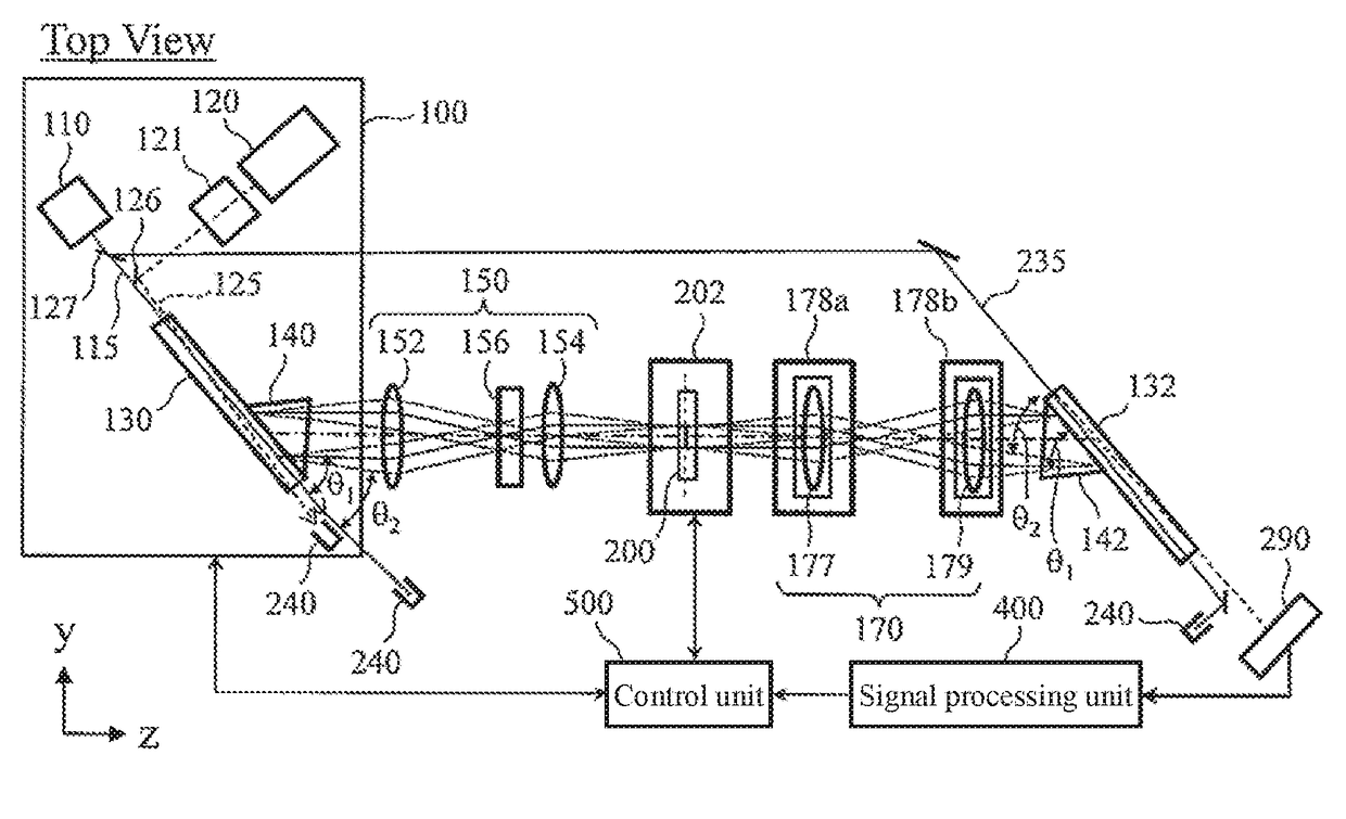
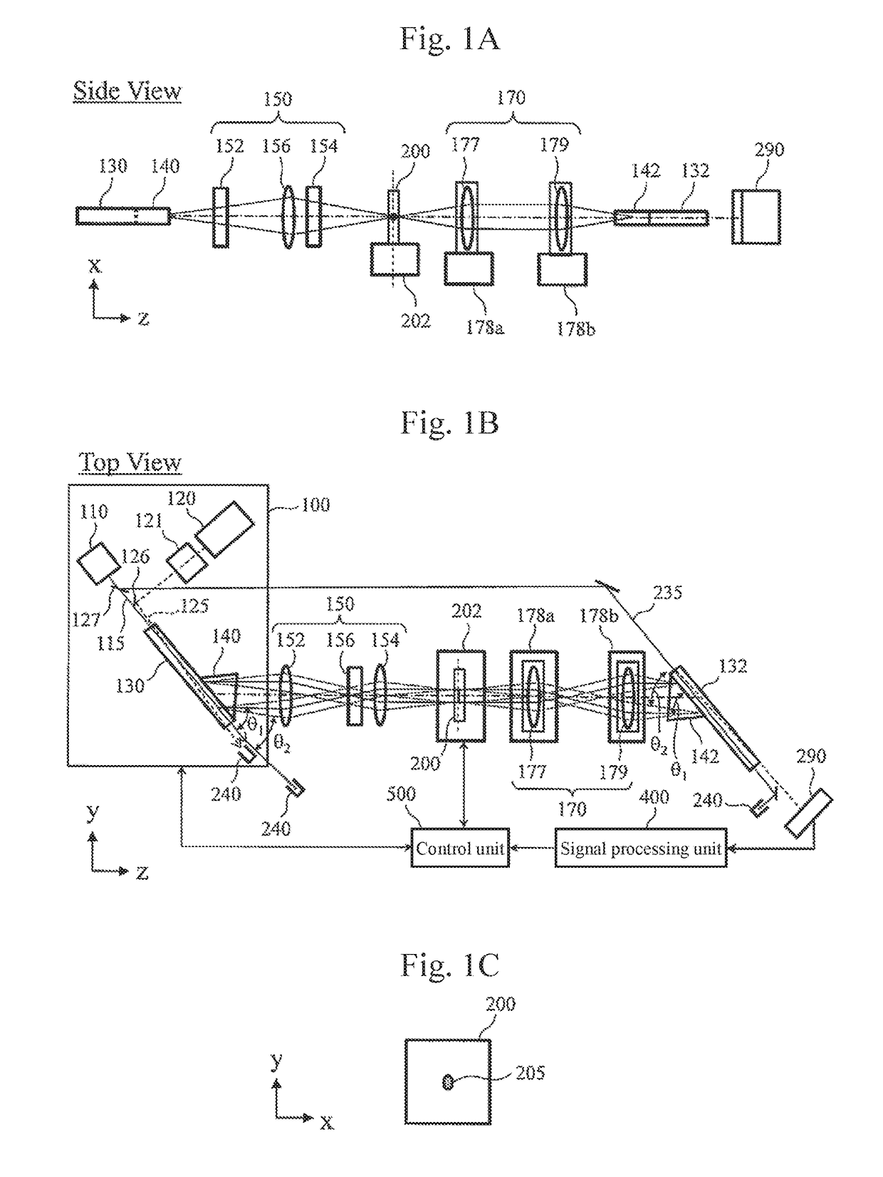
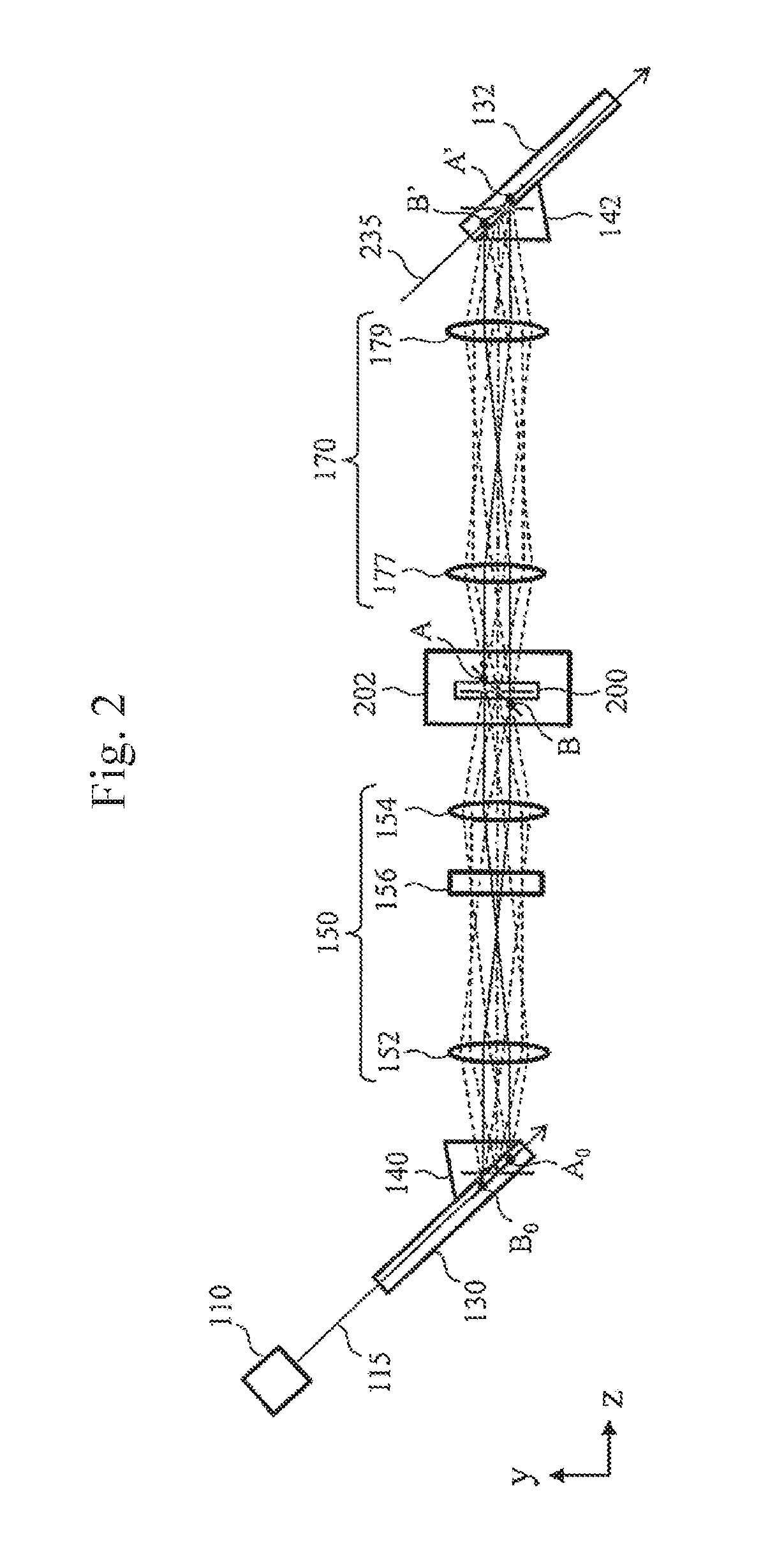
[0039]FIGS. 1A and 1B show examples of the overall configuration of a far-infrared spectroscopy device according to a first example. As an example, the far-infrared spectroscopy device is a device that measures the absorption spectrum of a sample 200 by using light transmitted through sample 200.
[0040]The far-infrared spectroscopy device includes a variable wavelength far-infrared light source 100 that generates far-infrared light, an illumination optical system 150 that emits far-infrared light to the sample 200, a sample stage 202 that mounts the sample 200, a far-infrared light imaging optical system 170 that images the far-infrared light from the sample 200 onto a nonlinear optical crystal for detection 132, the nonlinear optical crystal for detection 132 that converts the far-infrared light from sample 200 into near-infrared light by using pump light, a photo-detector (sensor) 290, a signal processing unit 400, and a control unit 500.
[0041]The variable wavelength far-infrared l...
second example
[0085]FIG. 6 shows a configuration of the spectroscopy device in a second example. Constituent elements described in the above example are denoted by the same reference numerals, and description thereof will be omitted. The difference from the first example in FIG. 1 is mainly (i) the configuration of the illumination optical system 150 and the far-infrared light imaging optical system 170, and (ii) arrangement of the nonlinear optical crystal for detection 132, and (iii) that the pump light used for generating far-infrared light passing through the nonlinear optical crystal 130 is guided to the nonlinear optical crystal for detection 132 and reused.
[0086]The light source 110 of the pump light 115 includes, as a main component, a short-pulse Q switch YAG laser 111, a polarization splitting system consisting of a polarization beam splitter (hereinafter, referred to as PBS) 114 and a quarter wavelength plate 116, and an amplifier unit (here, solid-state amplifier 118 in this case) tha...
third example
[0099]FIGS. 9A and 9B show examples of the overall configuration of the far-infrared spectroscopy device according to a third example. FIG. 9C is a plan view showing an irradiation region of a sample in the third example. Constituent elements described in the above example are denoted by the same reference numerals, and description thereof will be omitted.
[0100]In the far-infrared spectroscopy device of this example, an absorption spectrum is measured by using the reflected light of the sample 200. With the sample 200 surface as the center, the constituent elements from the variable wavelength far-infrared light source 100 to the illumination optical system 150 and the constituent elements after the far-infrared light imaging optical system 170 are inclined with respect to the plane of the sample 200. In the far-infrared spectroscopy device of this example, far-infrared light is incident obliquely on the sample 200, and the reflected light from the sample 200 is detected.
[0101]Accor...
PUM
| Property | Measurement | Unit |
|---|---|---|
| wavelength | aaaaa | aaaaa |
| wavelength | aaaaa | aaaaa |
| frequency | aaaaa | aaaaa |
Abstract
Description
Claims
Application Information
 - R&D Engineer
- R&D Manager
- IP Professional
- Industry Leading Data Capabilities
- Powerful AI technology
- Patent DNA Extraction
Browse by: Latest US Patents, China's latest patents, Technical Efficacy Thesaurus, Application Domain, Technology Topic.
© 2024 PatSnap. All rights reserved.Legal|Privacy policy|Modern Slavery Act Transparency Statement|Sitemap