Carbon dioxide removal system

a carbon dioxide and removal system technology, applied in the direction of liquid degasification by filtration, membranes, other medical devices, etc., can solve the problem that the extracorporeal blood treatment system does not have a heat exchanger adaptabl

Active Publication Date: 2018-08-23
MAQUET CARDIOPULMONARY GMBH
View PDF7 Cites 1 Cited by
  • Summary
  • Abstract
  • Description
  • Claims
  • Application Information

AI Technical Summary

Benefits of technology

[0109]The unique configuration of blood treatment system 1 of the present invention provides numerous operational and therapeutic advantages. Designed to accommodate a low rate of blood flow through gas exchange module 10, the blood treatment system 1 enables the use of minimally invasive small-lumen or dual-lumen cannulas to provide minimally traumatic vascular access. The low blood flow rate also results in low blood pressure conditions within the lumen of conduit 30, which reduces the potential for blood leakage from blood treatment system 1 as well as reduces the severity of the risk associated with blood leakage. Consequently, blood treatment system 1 need not require any or a plurality of highly sensitive, highly restrictive blood pressure and / or blood flow monitors for accessing the possibility of leakages, thereby simplifying the overall system.

Problems solved by technology

The extracorporeal blood treatment system does not have a heat exchanger adapted for regulating the temperature of the blood.

Method used


Image

  • Carbon dioxide removal system
  • Carbon dioxide removal system
  • Carbon dioxide removal system

Examples


example 1

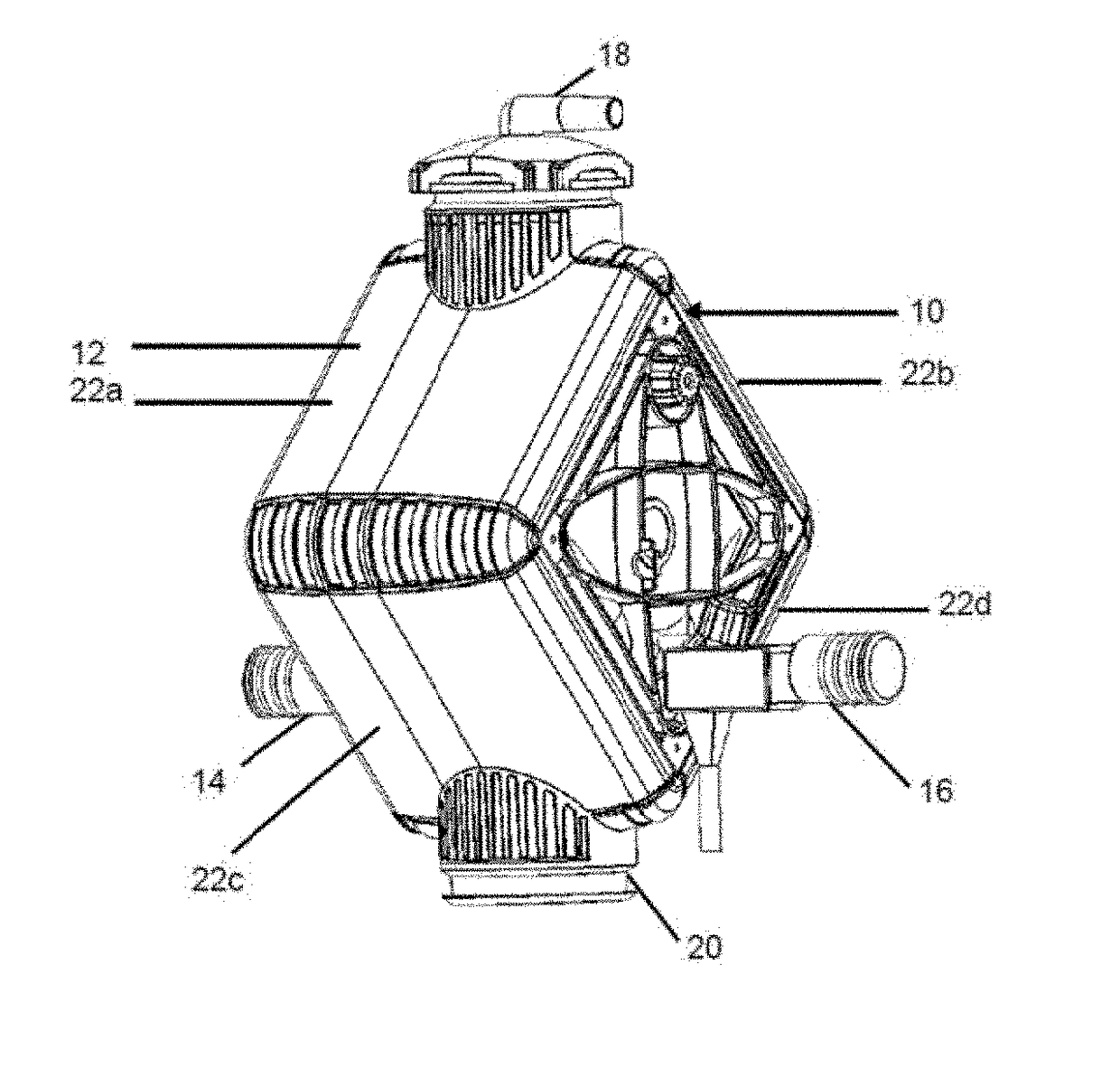
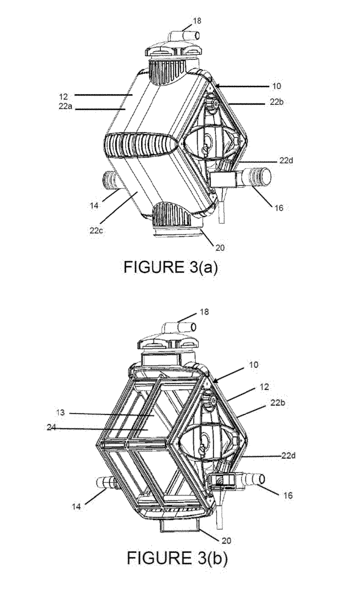
[0128]In one embodiment, gas exchange module 10 of the present invention has the same configuration as shown in FIGS. 3(a)-3(b), 3(d)-3(f) and 3(h)-3(m). Gas exchange module 10 included a gas exchange mat 34 constructed from 13,834 or more microporous gas permeable conduits 30 adapted for carbon dioxide diffusion. Conduits 30 were positioned parallel to one another to form conduit layers 32. The conduit layers 32 were stacked on top of one another to form gas exchange mat 34, each layer oriented perpendicular to an adjoining layer. All of the conduits 30 had an active length of about 5.5 cm and a total conduit length of about 7.6 cm. The active length percentage of conduit 30 capable of gas transfer was at most about 72.4%. Gas exchange mat 34 had a total gas exchange surface area of about 0.98 m2 and a conduit density of about 14,116 conduits per m2. The ratio of a maximum conduit active length to the 5.4 cm thickness of the gas exchange mat 34 (which can also be expressed here as ...

example 2

[0129]In one embodiment, gas exchange module 10 of the present invention has the same configuration as shown in FIGS. 3(a)-3(b), 3(d)-3(f) and 3(h)-3(m). Gas exchange module 10 included a gas exchange mat 34 constructed from 13,119 or more microporous gas permeable conduits 30 adapted for carbon dioxide diffusion. Conduits 30 were positioned parallel to one another to form conduit layers 32. The conduit layers 32 were stacked on top of one another to form gas exchange mat 34, each layer oriented perpendicular to an adjoining layer. All of the conduits 30 had an active length of about 5.8 cm and a total conduit length of about 7.6 cm. The active length percentage of conduit 30 capable of gas transfer was at most about 76.3%. Gas exchange mat 34 had a total gas exchange surface area of about 0.98 m2 and a conduit density of about 13,300 conduits per m2. The ratio of a maximum conduit active length to the 5.4 cm thickness of the gas exchange mat 34 (which can also be expressed here as ...

example 3

[0130]In one embodiment, gas exchange module 10 of the present invention has the same configuration as shown in FIGS. 3(a)-3(b), 3(d)-3(f) and 3(h)-3(m). Gas exchange module 10 included a gas exchange mat 34 constructed from 17,148 or more microporous gas permeable conduits 30 having an outer diameter of about 0.35 mm and is adapted for carbon dioxide diffusion. Conduits 30 were positioned parallel to one another to form conduit layers 32. The conduit layers 32 were stacked on top of one another to form gas exchange mat 34, each layer oriented perpendicular to an adjoining layer. All of the conduits 30 had an active length of about 5.2 cm and a total conduit length of about 7.6 cm. The active length percentage of conduit 30 capable of gas transfer was at most about 68.4%. Gas exchange mat 34 had a total gas exchange surface area of about 0.98 m2 and a conduit density of about 17,497 conduits per m2. The ratio of a maximum conduit active length to the 5.4 cm thickness of the gas exch...


PUM


Abstract

An extracorporeal blood treatment system including a gas exchange module operatively associated with a gas supply unit and optional pump for removing CO2 from blood. The gas exchange module includes a plurality of short conduits that are uniquely configured and arranged in a gas exchange mat to for efficient CO2 diffusion under conditions of low blood flow.

Description

[0001]This application is a continuation-in-part application pursuant to 35 U.S.C. 365(c) of International Application No. PCT / IB2014 / 001600, which claims benefit of priority to U.S. Provisional Patent Application No. 61 / 802,335, filed Mar. 15, 2013, and European Patent Application No. 13168103.3, filed May 16, 2013. The disclosures of these applications are herein incorporated by reference in their entirety.BACKGROUND OF THE INVENTION[0002]1. Field of the Invention[0003]The present invention is directed to a carbon dioxide removal system and methods for use thereof. In particular, the invention may be useful for treating diseases, syndromes, injuries, defects or other conditions affecting lung function, including chronic obstructive pulmonary disease (COPD), chronic and acute hypercapnia, respiratory acidosis, acute lung injury (ALI), and acute respiratory distress syndrome (ARDS).[0004]2. Description of the Related Technology[0005]The primary functions of the lung are oxygenation ...

Claims


Application Information

Patent Timeline
Patent Type & Authority Applications(United States)
IPC IPC(8): A61M1/36
CPCA61M1/3627A61M1/1698B01D19/0031B01D63/026B01D2313/90A61M1/3666A61M2205/3334A61M2205/3368A61M2230/202A61M2230/205A61M2230/208A61M1/3609B01D2313/60
Inventor HAAG, ULRICHMOLLENBERG, OLIVERTHOLKE, RALFNAKEL, MATHIASKOBER, RUDOLF
Owner MAQUET CARDIOPULMONARY GMBH
Why Eureka
Try Eureka