
Luminescent Substrate Containing Abrasive Particles, and Method for the Production Thereof

Active Publication Date: 2018-09-13
COMMISSARIAT A LENERGIE ATOMIQUE ET AUX ENERGIES ALTERNATIVES +1
View PDF1 Cites 0 Cited by
  • Summary
  • Abstract
  • Description
  • Claims
  • Application Information

AI Technical Summary

Benefits of technology

The patent describes an abrasive device that has been developed to make it easier to monitor its surface condition. This allows for better control of the device during manufacturing and use. The hardness of the binder or coating can be improved by adding sulfur, and the particles, particularly nanoparticles, can be coated with polysiloxane or silicon oxide to improve their dispersibility and stability in the binder. The coating can also be made of cobalt, a metal with good abrasion resistance. The abrasive substrate can undergo a lapping step to improve its performance.

Problems solved by technology

However, the absence of contrast and of relief between the particles and the substrate complicates any accurate monitoring of the wearing of abrasive devices.

Method used


Image

  • Luminescent Substrate Containing Abrasive Particles, and Method for the Production Thereof
  • Luminescent Substrate Containing Abrasive Particles, and Method for the Production Thereof
  • Luminescent Substrate Containing Abrasive Particles, and Method for the Production Thereof

Examples


Embodiment Construction

[0119]The presently described embodiments provide significant advantages in the regular control of the abrasive properties of the abrasive substrate.

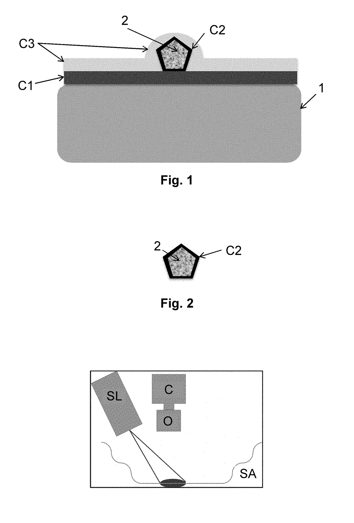
[0120]FIG. 1 shows a substrate (1) comprising a sawing or polishing abrasive, comprising:

[0121]a substrate (1);

[0122]a binder C1 covering the substrate (1);

[0123]abrasive particles (2) having a coating C2;

[0124]a coating C3 coating binder C1 and the abrasive particles (2) coated with C2.

[0125]The abrasive particles (2) coated with C2 (FIG. 2) are in contact with binder C1 and with coating C3.

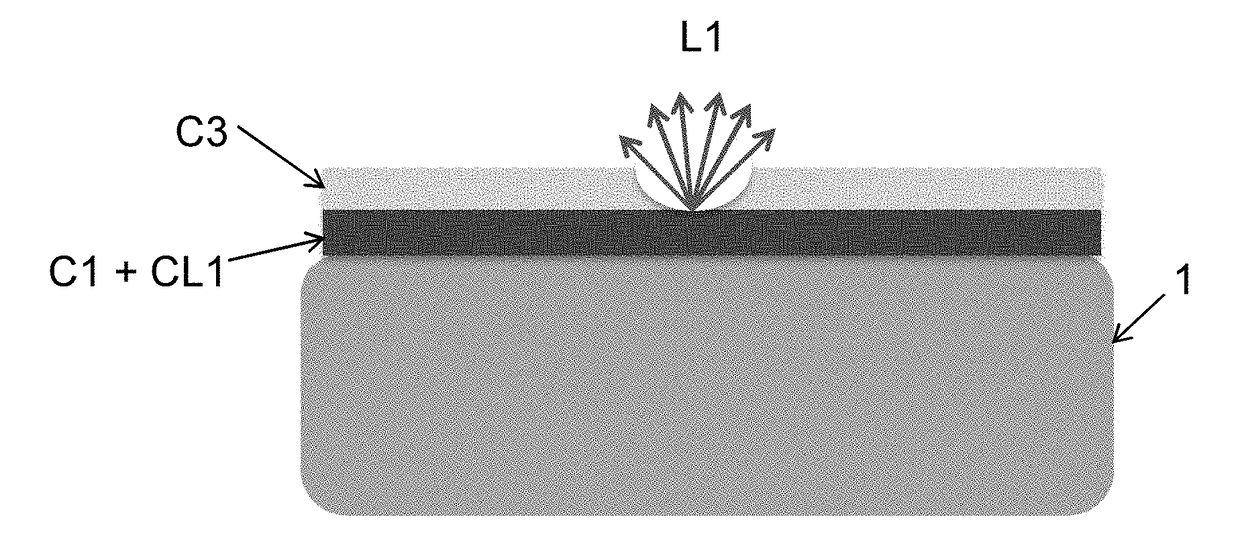
[0126]In embodiments, the abrasive substrate may comprise at least one light-emitting compound CL in binder C1 and / or in coating C2 and / or in coating C3.

[0127]Thus, to obtain different data relative to the abrasive substrate, the fluorescence signal may be dissociated on the three layers C1, C2, and C3.

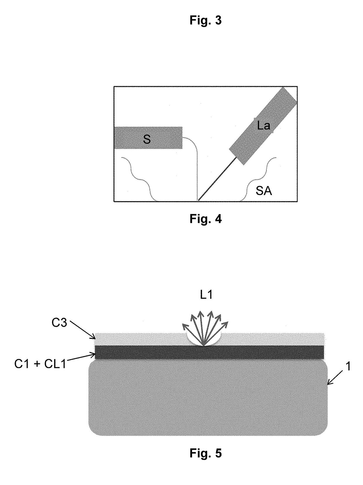
[0128]As illustrated in FIGS. 3 and 4, the presence of light-emitting compound CL may be detected due to different devices. The quality control and t...


PUM


Abstract

An abrasive sawing or polishing substrate includes a substrate, a binder C1 covering at least a portion of the substrate, and abrasive particles having an at least partial coating, C2. The abrasive sawing or polishing substrate also includes a coating C3 coating binder C1 and the abrasive particles coated with C2 and at least one light-emitting compound. The abrasive particles coated with C2 are in contact with binder C1 and with coating C3.

Description

FIELD OF TECHNOLOGY[0001]The present disclosure relates to a substrate, for example, a wire, containing abrasive particles and a light-emitting compound.[0002]The field of use of the presently described embodiments particularly concerns the sawing and the polishing of materials such as silicon, sapphire, or silicon carbide.BACKGROUND[0003]Generally, abrasive devices are manufactured by arranging abrasive particles on a substrate by means of a binder.[0004]This technique enables to obtain sawing or polishing devices, for example, polishing pads, cutting or polishing wheels, or cutting wires.[0005]The binder enables to attach the abrasive particles to the substrate. It is generally made of resin or of metal.[0006]However, the absence of contrast and of relief between the particles and the substrate complicates any accurate monitoring of the wearing of abrasive devices.SUMMARY OF THE DISCLOSURE[0007]The described embodiments enable to solve this problem by integrating a light-emitting ...

Claims


Application Information

Patent Timeline
IPC IPC(8): B24D3/34B24D18/00
CPCB24D3/346B24D18/0018B24B49/12B24D3/34
Inventor DEBOURDEAU, MATHIEUCHABLI, AMALCOUSTIER, FABRICELAGUITTON, BRUNOSIMONATO, JEAN-PIERRE
Owner COMMISSARIAT A LENERGIE ATOMIQUE ET AUX ENERGIES ALTERNATIVES
Learn More