System And Method For Isolation Of Load Dynamics In Motor Drive Tuning

a technology of load dynamics and motor drive, applied in the field of motor drive tuning, can solve the problems of inability to identify the number of units, the number of units is unknown, and the process of selecting the controller and the gain value of the associated controller may be complex and laborious

Active Publication Date: 2018-09-13
ROCKWELL AUTOMATION TECH
View PDF6 Cites 9 Cited by
  • Summary
  • Abstract
  • Description
  • Claims
  • Application Information

AI Technical Summary

Benefits of technology

[0014]Thus, it would also be desirable to provide a motor drive that provides initial settings which provide acce

Problems solved by technology

However, selecting the controllers and associated controller gain values may be a complex process.
The interaction of controller gain values often requires a time and labor-intensive iterative approach to selecting gain values in order to achieve the desired level of performance.
However, these quantities are unknown and skilled technicians must manually adjust the gain values for several control loops and/or an observer to achieve satisfactory performance.
This manual tuning process takes time, requires a high skill level, and adds significant cost.
For example, a coupling with a small level of compliance and a high ratio of load inertia to motor inertia typically results in significantly lower controller gain values than for the same coupling and a low ratio of load inertia to motor inertia.
Consequently, varying levels of compliance and/or backlash result in a unique set of controller gain values for each application.
Successfully setting the controller gain values to achieve a desired level of performance for each application typically takes time and requires a skilled technician.
Many companies don't have such a technician and may need to hire a field service technician from the manufacturer of the motor drive.
This can add significantly to the cost to start up and commission a new control system.
However, the reduced performance level may result in lost revenue during operatio

Method used


Image

  • System And Method For Isolation Of Load Dynamics In Motor Drive Tuning
  • System And Method For Isolation Of Load Dynamics In Motor Drive Tuning
  • System And Method For Isolation Of Load Dynamics In Motor Drive Tuning

Examples


Embodiment Construction

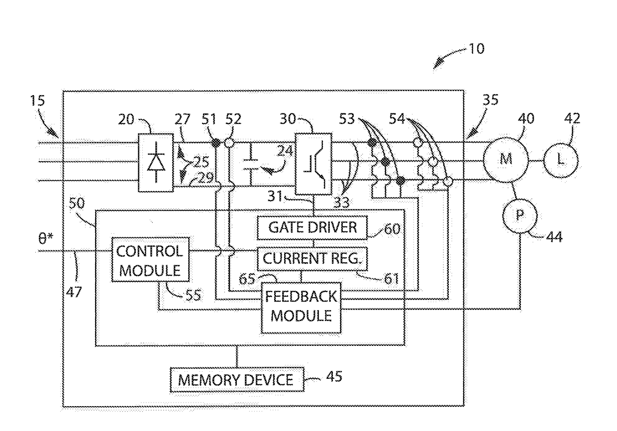
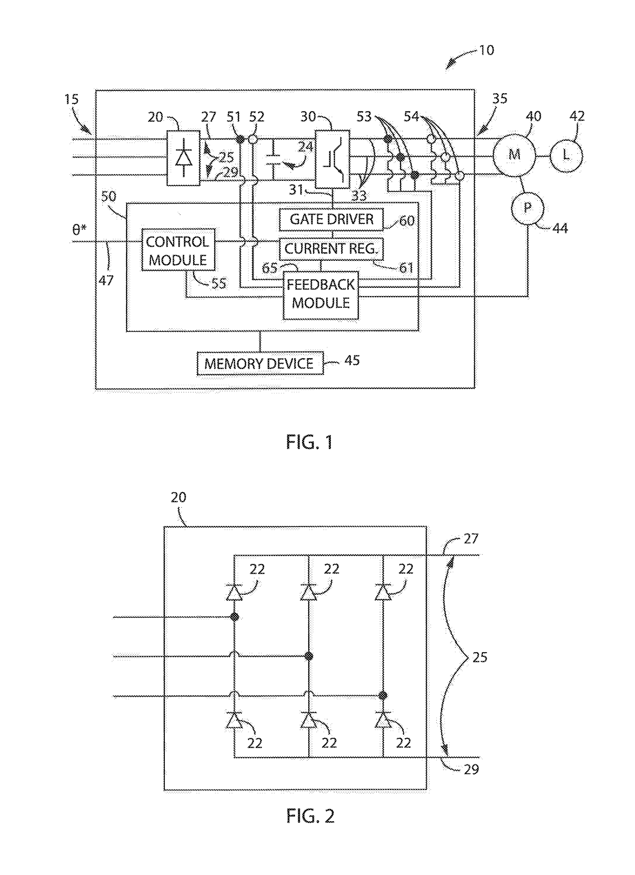
[0029]Turning initially to FIG. 1, a motor drive 10, according to one embodiment of the invention, is configured to receive a three-phase AC voltage at an input 15 of the motor drive 10 which is, in turn, provided to a rectifier section 20 of the motor drive 10. The rectifier section 20 may include any electronic device suitable for passive or active rectification as is understood in the art. With reference also to FIG. 2, the illustrated rectifier section 20 includes a set of diodes 22 forming a diode bridge that rectifies the three-phase AC voltage to a DC voltage on the DC bus 25. Optionally, the rectifier section 20 may include other solid state devices including, but not limited to, thyristors, silicon controlled rectifiers (SCRs), or transistors to convert the input power 15 to a DC voltage for the DC bus 25. The DC voltage is present between a positive rail 27 and a negative rail 29 of the DC bus 25. A DC bus capacitor 24 is connected between the positive and negative rails, ...


PUM


Abstract

A motor drive having controller settings which will result in improved tuning-less performance is disclosed. Gain values for the control loops and/or observer are determined independently of the mechanical loading and the resultant effects of that loading on the motor. The motor drive includes a control loop operable to receive a command signal and to generate a controller reference signal to achieve desired operation of a motor connected to the motor drive. The motor drive also includes a load observer operable to generate a signal that estimates a response required by the motor drive as a result of a load present on the motor. The response estimate signal is provided to the controller to isolate the effects of the load dynamics from operation of the control loops within the controller. A modified controller reference signal is generated as a function of the response estimate signal and the controller reference signal.

Description

CROSS-REFERENCE TO RELATED APPLICATIONS[0001]This application is a continuation-in-part of U.S. patent application Ser. No. 14 / 842,538, filed Sep. 1, 2015 and entitled System and Method for Improved Motor Drive Tuning, the entire contents of which is incorporated herein by reference.BACKGROUND OF THE INVENTION[0002]The subject matter disclosed herein relates generally to tuning a motor drive and, more specifically, to a method to isolate the effects of mechanical loading to simplify initial tuning and improve performance in a motor drive system.[0003]As is known to those skilled in the art, motor drives are utilized to control operation of a motor. According to one common configuration, a motor drive includes a DC bus having a DC voltage of suitable magnitude from which an AC voltage may be generated and provided to the motor. The DC voltage may be provided as an input to the motor drive or, alternately, the motor drive may include a rectifier section which converts an AC voltage in...

Claims


Application Information

Patent Timeline
IPC IPC(8): H02P23/12H02P23/14
CPCH02P23/12H02P23/14H02P23/20G05B2219/37388G05B2219/40358G05B2219/42161
Inventor MIKLOSOVIC, ROBERT J.FAST, BRIANCHAFFEE, MARK
Owner ROCKWELL AUTOMATION TECH
Why Eureka
Try Eureka