Magnetic tape device, magnetic reproducing method, and head tracking servo method

a technology of magnetic reproducing and magnetic tape, which is applied in the direction of recording on magnetic tapes, maintaining head carrier alignment, instruments, etc., can solve the problems of weak magnetic signal obtained from a magnetic layer, specifically leakage magnetic field, etc., and achieve the effect of decreasing reducing the resistance value of the tmr head

Active Publication Date: 2018-10-04
FUJIFILM CORP
View PDF0 Cites 105 Cited by
  • Summary
  • Abstract
  • Description
  • Claims
  • Application Information

AI Technical Summary

Benefits of technology

[0038]According to one aspect of the invention, it is possible to perform the reproduction at a high SNR, in a case of reproducing information recorded on the magnetic tape with the TMR head at the magnetic tape transportation speed equal to or lower than 18 m/sec, and to prevent occurrence of a significant decrease in resistance value in the TMR head.
[003

Problems solved by technology

However, as the recording density increases, a magnetic signal (specifically,

Method used


Image

  • Magnetic tape device, magnetic reproducing method, and head tracking servo method
  • Magnetic tape device, magnetic reproducing method, and head tracking servo method
  • Magnetic tape device, magnetic reproducing method, and head tracking servo method

Examples


examples

[0224]Hereinafter, the invention will be described with reference to examples. However, the invention is not limited to aspects shown in the examples. “Parts” and “%” in the following description mean “parts by mass” and “mass %”, unless otherwise noted. In addition, steps and evaluations described below are performed in an environment of an atmosphere temperature of 23° C.±1° C., unless otherwise noted.

[0225]Examples and Comparative Examples According to First Aspect

example 1-1

[0226]1. Manufacturing of Magnetic Tape

[0227](1) Preparation of Alumina Dispersion

[0228]3.0 parts of 2,3-dihydroxynaphthalene (manufactured by Tokyo Chemical Industry Co., Ltd.), 31.3 parts of a 32% solution (solvent is a mixed solvent of methyl ethyl ketone and toluene) of a polyester polyurethane resin having a SO3Na group as a polar group (UR-4800 (amount of a polar group: 80 meq / kg) manufactured by Toyobo Co., Ltd.), and 570.0 parts of a mixed solution of methyl ethyl ketone and cyclohexanone (mass ratio of 1:1) as a solvent were mixed in 100.0 parts of alumina powder (HIT-80 manufactured by Sumitomo Chemical Co., Ltd.) having an gelatinization ratio of 65% and a BET specific surface area of 30 m2 / g, and dispersed in the presence of zirconia beads by a paint shaker for 5 hours. After the dispersion, the dispersion liquid and the beads were separated by a mesh and an alumina dispersion was obtained.

[0229](2) Magnetic Layer Forming Composition List

[0230]Magnetic Solution

[0231]Ferr...

examples 1-2 to 1-10

and Comparative Examples 1-1 to 1-12

[0335]1. Manufacturing of Magnetic Tape

[0336]A magnetic tape was manufactured in the same manner as in Example 1-1, except that various conditions shown in Table 5 were changed as shown in Table 5.

[0337]In Table 5, in the comparative examples in which “none” is shown in a column of the orientation, the magnetic layer was formed without performing the orientation process in the same manner as in Example 1-1.

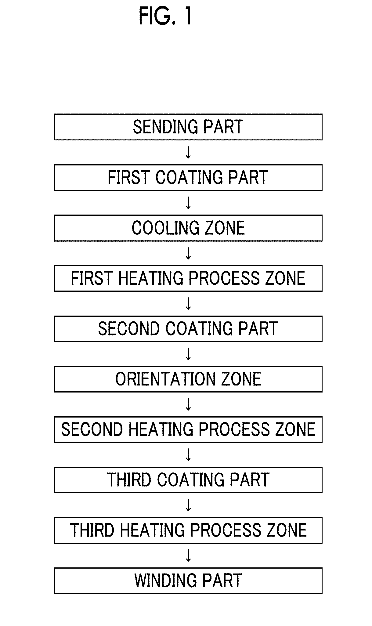
[0338]In the examples in which “longitudinal” is disclosed in a column of the orientation, the cooling step was performed by passing the coating layer through the cooling zone in which the atmosphere temperature is adjusted to 0° C. for the staying time shown in Table 5 while the coating layer of the magnetic layer forming composition is wet, and then, a longitudinal orientation process was performed by applying a magnetic field having a magnetic field strength of 0.3 T to the surface of the coating layer in a longitudinal direction. After that,...


PUM


Abstract

Provided is a magnetic tape device in which a magnetic tape transportation speed is equal to or lower than 18 m/sec, Ra measured regarding a surface of a magnetic layer of a magnetic tape is equal to or smaller than 2.0 nm, a C—H derived C concentration calculated from a C—H peak area ratio of C1s spectra obtained by X-ray photoelectron spectroscopic analysis performed on the surface of the magnetic layer at a photoelectron take-off angle of 10 degrees is 45 to 65 atom %, and ΔSFD (=SFD25° C.−SFD−190° C.) in a longitudinal direction of the magnetic tape is equal to or smaller than 0.50, with the SFD25° C. being SFD measured in a longitudinal direction of the magnetic tape at a temperature of 25° C., and the SFD−19° C. being SFD measured at a temperature of −190° C.

Description

CROSS-REFERENCE TO RELATED APPLICATIONS[0001]This application claims priority under 35 U.S.C 119 to Japanese Patent Application No. 2017-065730 filed on Mar. 29, 2017. The above application is hereby expressly incorporated by reference, in its entirety, into the present application.BACKGROUND OF THE INVENTION1. Field of the Invention[0002]The present invention relates to a magnetic tape device, a magnetic reproducing method, and a head tracking servo method.2. Description of the Related Art[0003]Magnetic recording is used as a method of recording information on a recording medium. In the magnetic recording, information is recorded on a magnetic recording medium as a magnetized pattern. Information recorded on a magnetic recording medium is reproduced by reading a magnetic signal obtained from the magnetized pattern by a magnetic head. As a magnetic head used for such reproducing, various magnetic heads have been proposed (for example, see JP2004-185676A).SUMMARY OF THE INVENTION[000...

Claims


Application Information

Patent Timeline
IPC IPC(8): G11B5/706G11B5/584G11B5/008
CPCG11B5/70626G11B5/584G11B5/00817G11B5/70615G11B5/70G11B5/71G11B5/78
Inventor KASADA, NORIHITOOZAWA, EIKI
Owner FUJIFILM CORP
Why Eureka
Try Eureka