
Structure and method to fabricate highly reactive physical vapor deposition target

a physical vapor deposition and target technology, applied in vacuum evaporation coatings, electric discharge tubes, coatings, etc., can solve the problems of significant burn-in time required to clean, significantly reduce the overall tool utilization rate, and the clean-up process is typically long in duration

Active Publication Date: 2018-11-01
IBM CORP
View PDF4 Cites 3 Cited by
  • Summary
  • Abstract
  • Description
  • Claims
  • Application Information

AI Technical Summary

Benefits of technology

The patent describes a way to protect a target from exposure to oxygen and moisture during a chemical vapor deposition process. This is achieved by using a sacrificial non-reactive cap made of materials like titanium oxide or aluminum oxide. The cap is placed on the target to prevent reaction with the atmosphere and absorption of oxygen and water, which can make the target difficult to prepare for deposition. This cap is removed once the target is in the chamber, allowing it to be ready for deposition without excessive clean-up time. The non-reactive cap layer can also include metal or metal oxides, and can be formed using plating, sputtering, or chemical vapor deposition methods. Overall, this approach improves the efficiency and quality of chemical vapor deposition processes.

Problems solved by technology

After initial installation of a new target, there is a significant burn-in time required to clean up water or oxidation on surfaces of the highly reactive target.
The clean-up process is typically long in duration and can significantly reduce overall tool utilization.
Without the proper clean-up process, it can be difficult to provide high purity low defect coatings.
Additionally, without the proper clean-up process it can be difficult to provide for consistent manufacturing of devices including the coatings produced from highly reactive physical vapor deposition (PVD) targets.
Further, deficiencies in coating purity can have negative impact on electrical devices including the coating.

Method used


Image

  • Structure and method to fabricate highly reactive physical vapor deposition target
  • Structure and method to fabricate highly reactive physical vapor deposition target
  • Structure and method to fabricate highly reactive physical vapor deposition target

Examples


Embodiment Construction

[0013]Detailed embodiments of the claimed structures and methods are disclosed herein; however, it is to be understood that the disclosed embodiments are merely illustrative of the claimed structures and methods that may be embodied in various forms. In addition, each of the examples given in connection with the various embodiments are intended to be illustrative, and not restrictive. Further, the figures are not necessarily to scale, some features may be exaggerated to show details of particular components. Therefore, specific structural and functional details disclosed herein are not to be interpreted as limiting, but merely as a representative basis for teaching one skilled in the art to variously employ the methods and structures of the present disclosure.

[0014]References in the specification to “one embodiment”, “an embodiment”, “an example embodiment”, etc., indicate that the embodiment described may include a particular feature, structure, or characteristic, but every embodim...


PUM

PropertyMeasurementUnit
thicknessaaaaaaaaaa
thicknessaaaaaaaaaa
total thicknessaaaaaaaaaa

Abstract

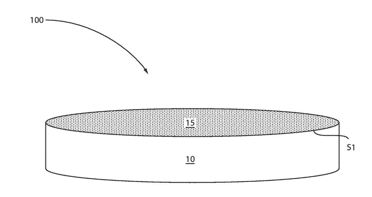
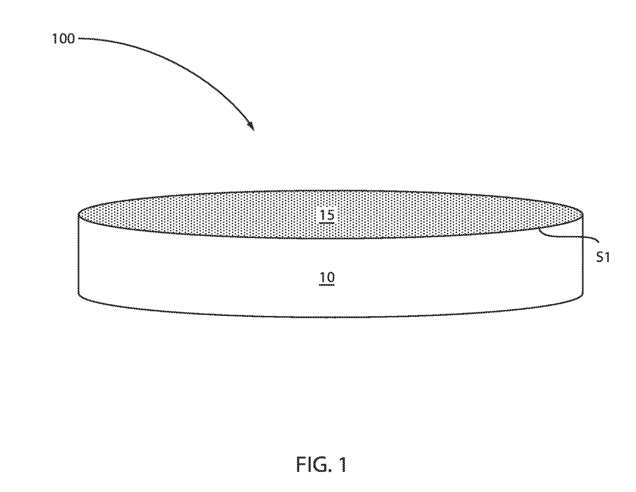
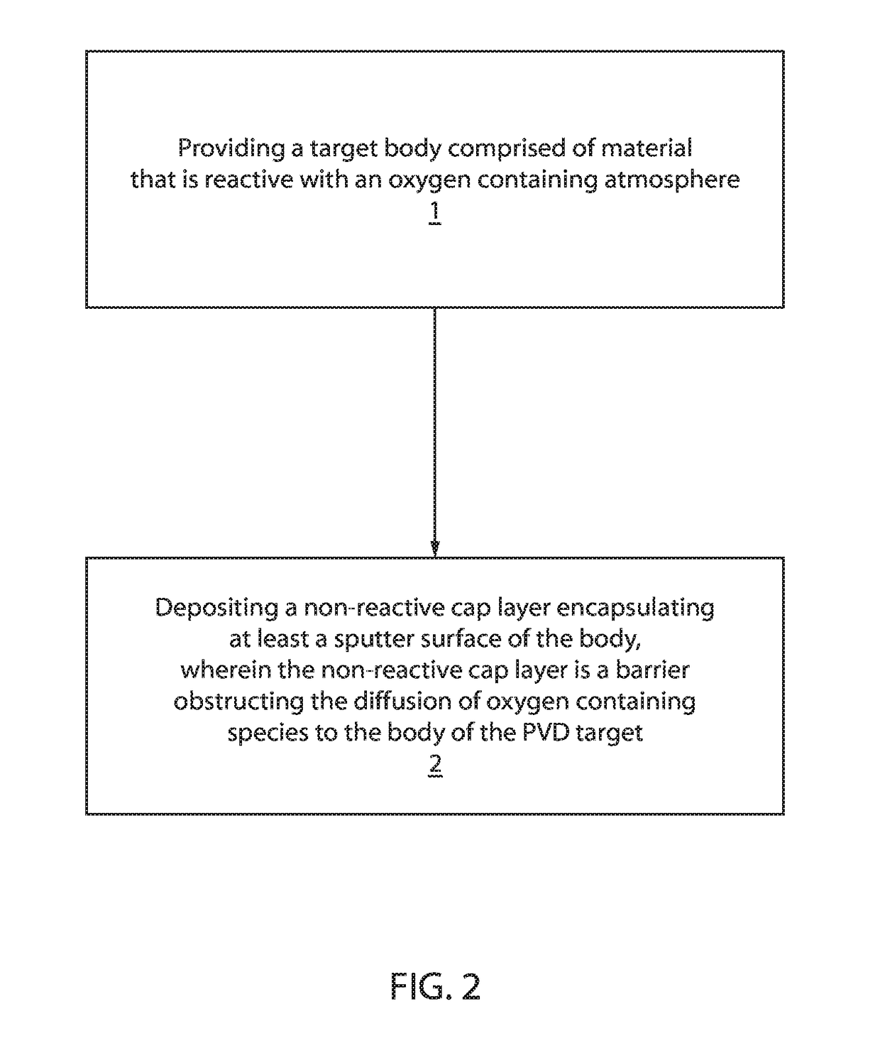
A physical vapor deposition (PVD) target that includes a body composed of material that is reactive with an oxygen containing atmosphere; and a non-reactive cap layer encapsulating at least a sputter surface of the body. The non-reactive cap layer is a barrier obstructing the diffusion of oxygen containing species to the body of the PVD target.

Description

BACKGROUNDTechnical Field[0001]The methods and structures described herein relate to semiconductor processing and tools, and more particularly to a physical vapor deposition tool and method for use that provides protection for highly reactive source materials.Related Art[0002]Highly reactive physical vapor deposition (PVD) targets such as, e.g., Magnesium Oxide (MgO) and Lanthanum (La) can absorb water or oxidize very quickly during exposure to air. After initial installation of a new target, there is a significant burn-in time required to clean up water or oxidation on surfaces of the highly reactive target. The clean-up process is needed to prepare the target for deposition of high quality materials. The clean-up process is typically long in duration and can significantly reduce overall tool utilization. Without the proper clean-up process, it can be difficult to provide high purity low defect coatings. Additionally, without the proper clean-up process it can be difficult to provi...

Claims


Application Information

Patent Timeline
Patent Type & Authority Applications(United States)
IPC IPC(8): C23C14/34C23C14/14C23C14/08
CPCC23C14/3414C23C14/082C23C14/14C23C14/081H01J37/3491H01J37/3426C23C14/06
Inventor BROWN, STEPHEN L.DORIS, BRUCE B.REUTER, MARK C.
Owner IBM CORP
Learn More