Variable focal length lens device

a lens device and variable technology, applied in the field of variable focal length lens devices, can solve the problems of not being able to efficiently form the standing wave, and achieve the effects of preventing unintended operation, efficient use, and screen spa

Active Publication Date: 2018-11-01
MITUTOYO CORP
View PDF0 Cites 7 Cited by
  • Summary
  • Abstract
  • Description
  • Claims
  • Application Information

AI Technical Summary

Benefits of technology

[0014]An object of the invention is to provide a variable focal length lens device capable of appropriately setting control items of a lens system and a pulsed light illuminator and appropriately operating the lens system and the pulsed light illuminator.
[0016]According to the above aspect of the invention, while the standing wave is formed in the lens system in response to the drive signal from the lens controller (resonant state), the image detector detects the image at a predetermined image-detection timing to obtain the image at a desired focal length. Further, when the resonance-lock operation unit enables the resonance-lock controller, the frequency of the drive signal is automatically tuned to the peak of the current resonance frequency of the lens system to efficiently form the standing wave.
[0019]In the above arrangement, the lens controller is constructed as a dedicated hardware so that the components for directly controlling the operation of the lens system and the pulsed light illuminator (i.e. controlling the frequency and amplitude, controlling the maximum drive voltage and the like) can be concentrated in the dedicated hardware. On the other hand, the lens controller is controlled using the lens operation unit in a form of the versatile personal computer, which runs a dedicated software to achieve operations for each of the functions and is adapted to be easily modified in accordance with the application of the lens operation unit.
[0021]In the above arrangement, the setting of the frequency and the amplitude of the drive signal, and enabling / disabling of the resonance-lock controller, which are often used during the operation of the lens system, can be done on the usually displayed main screen. In contrast, the setting of the image-detection timing of the image detector (setting of the synchronization output signal control) and the setting of the maximum drive voltage of the drive signal, which are not likely to be changed after once being set, are made on the sub screens. Accordingly, the screen space can be efficiently used and unintended operation can be prevented.
[0022]According to the invention, a variable focal length lens device capable of appropriately setting control items of a lens system and a pulsed light illuminator and appropriately controlling the lens system and the pulsed light illuminator can be provided.

Problems solved by technology

If the drive signal inputted to the lens system remains the same as the drive signal before the temperature change, the drive signal is deviated from a peak of the resonance frequency, thus failing to efficiently form the standing wave.

Method used


Image

  • Variable focal length lens device
  • Variable focal length lens device
  • Variable focal length lens device

Examples


Embodiment Construction

)

[0049]Exemplary embodiment(s) of the invention will be described below with reference to the attached drawings.

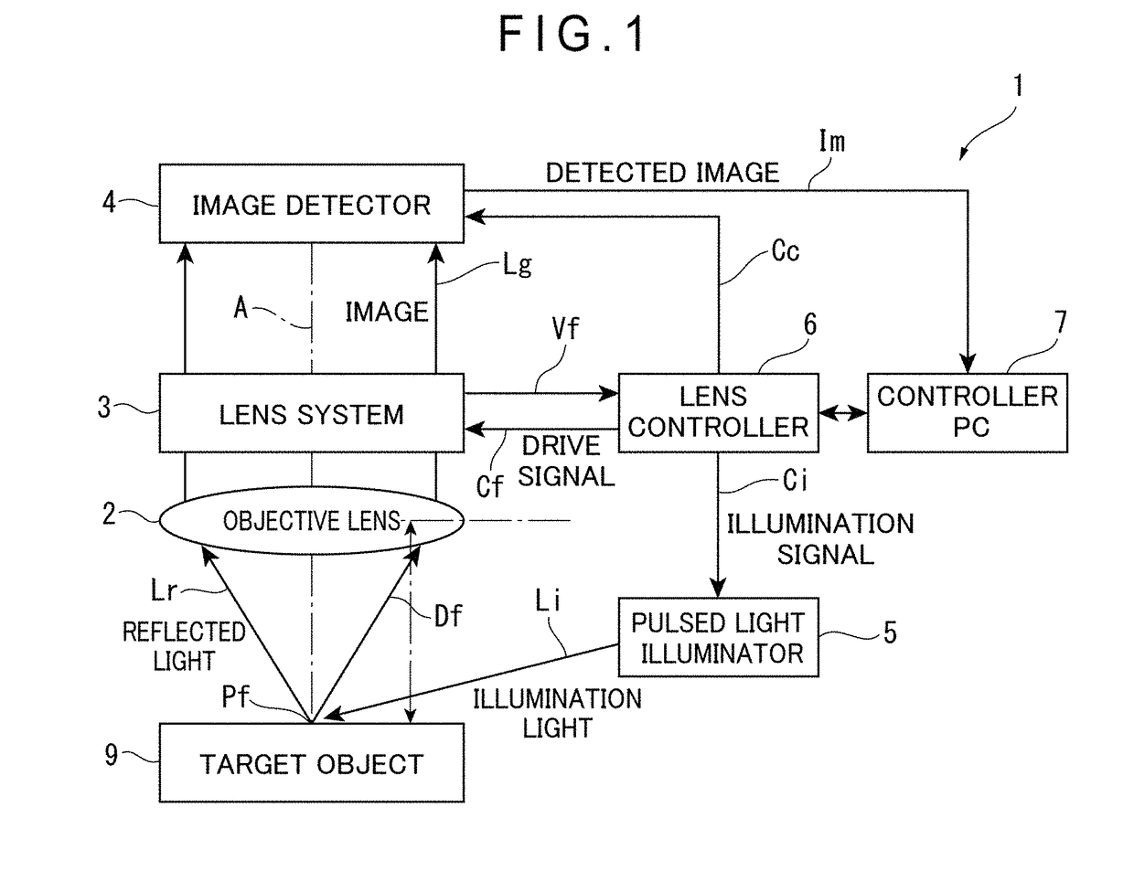
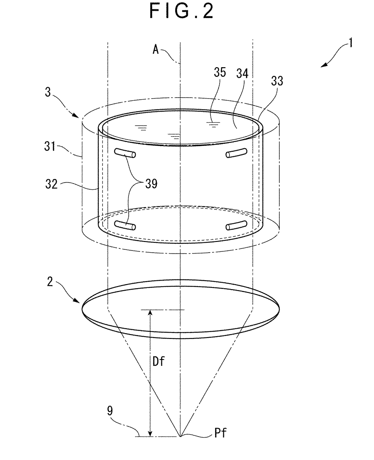
[0050]As shown in FIG. 1, in order to detect an image of a surface of a target object 9 while changing a focal length, a variable focal length lens device 1 includes: an objective lens 2; a lens system 3; and an image detector 4, the objective lens 2, the lens system 3 and the image detector 4 being disposed on a common optical axis A intersecting the surface of the target object 9.

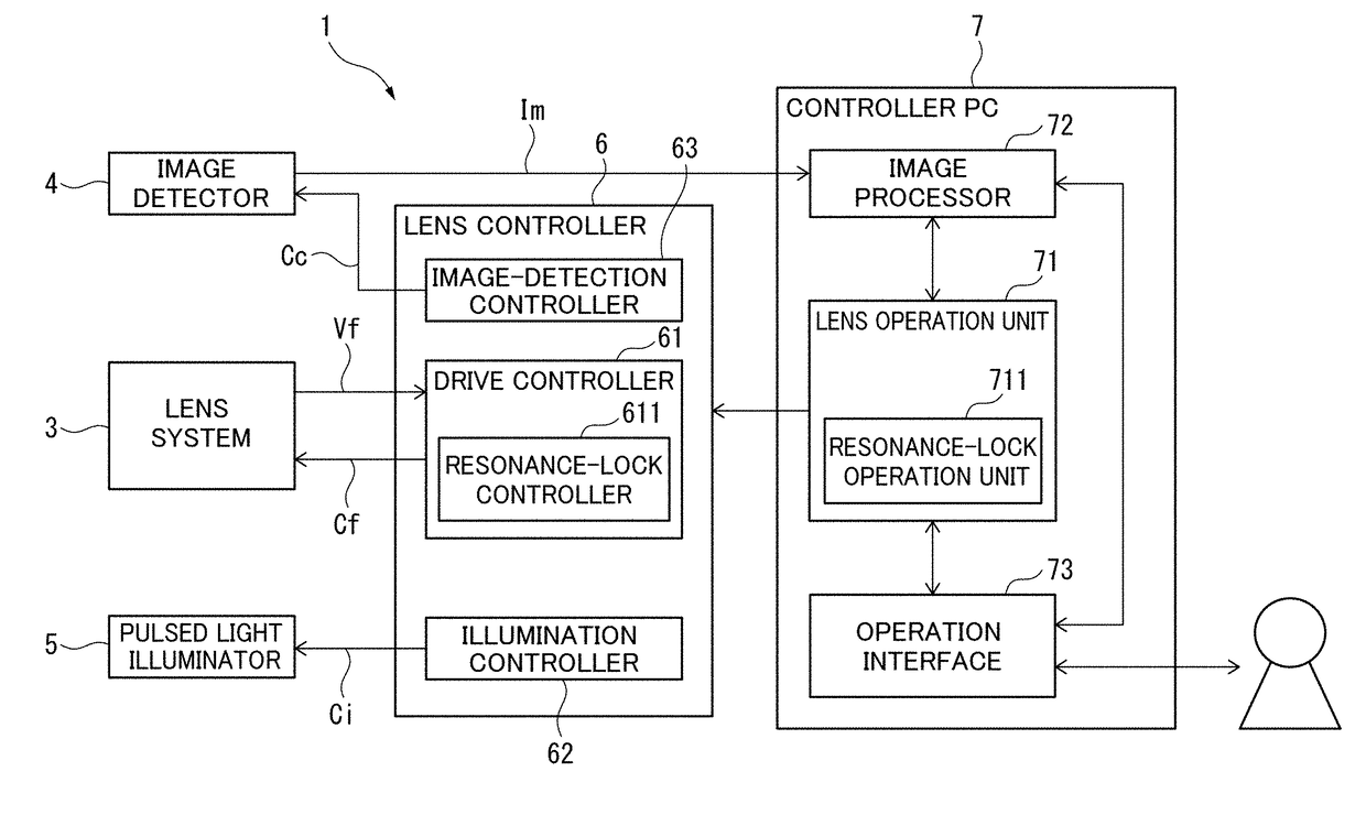
[0051]The variable focal length lens device 1 further includes: a pulsed light illuminator 5 configured to apply pulsed illumination on the surface of the target object 9; a lens controller 6 configured to control operations of the lens system 3 and the pulsed light illuminator 5; and a controller PC 7 configured to operate the lens controller 6.

[0052]An existing personal computer is used as the controller PC 7. The desired function of the controller PC 7 is achieved by running a predetermined c...


PUM


Abstract

A variable focal length lens device includes: a lens system whose refractive index is variable in response to an inputted drive signal; an image detector for detecting an image of a target object through the lens system; a lens controller for outputting the drive signal and an illumination signal; and a lens operation unit for adjusting a frequency and amplitude of the drive signal outputted by the lens controller and an image-detection timing for the image detector. The lens controller includes a resonance-lock controller for tuning the drive signal to a resonance frequency of the lens system. The lens operation unit includes a resonance-lock operation unit for switchably enabling and suspending the resonance-lock controller.

Description

[0001]The entire disclosure of Japanese Patent Application No. 2017-089578 filed Apr. 28, 2017 is expressly incorporated by reference herein.TECHNICAL FIELD[0002]The present invention relates to a variable focal length lens device.BACKGROUND ART[0003]A variable focal length lens device employing, for instance, a liquid lens system (simply referred to as a “lens system” hereinafter) based on a principle disclosed in Patent Literature 1 (U.S. Pre-Grant Patent Publication No. 2010 / 0177376) has been developed.[0004]The lens system includes a cylindrical oscillator made of a piezoelectric material that is immersed in a transparent liquid. When an alternating-current (AC) voltage is applied to an inner circumferential surface and an outer circumferential surface of the oscillator of the lens system, the oscillator expands and contracts in a thickness direction thereof to oscillate the liquid inside the oscillator. Then, when the frequency of the applied AC voltage is tuned to an intrinsic...

Claims


Application Information

Patent Timeline
Patent Type & Authority Applications(United States)
IPC IPC(8): G02B7/10H04N5/225H04N5/232G06F3/048G02B15/14
CPCG02B7/102H04N5/2254H04N5/2256H04N5/23216G06F3/048G02B15/14G02B3/0081G02B3/14G02F1/13306G02F1/29G02F1/294G02B7/04G02B15/04H04N23/56H04N23/66H04N23/55H04N23/62
Inventor SAKAI, HIROSHIWATANABE, YUTAKA
Owner MITUTOYO CORP
Why Eureka
Try Eureka