
Apparatus and method for processing bio optical signal using spread spectrum

a bio optical signal and spread spectrum technology, applied in the field of apparatus and method for processing bio optical signals, can solve the problems of reducing the detection sensitivity of the raman spectroscopy apparatus using deteriorating performance of sensing and image technology, and difficult to guarantee the stable function of separating a raman scattering signal and a noise signal, so as to improve the performance of sensing and imaging technology, increase the resolution and the effect of signal-to-

Active Publication Date: 2018-11-15
ELECTRONICS & TELECOMM RES INST +1
View PDF1 Cites 3 Cited by
  • Summary
  • Abstract
  • Description
  • Claims
  • Application Information

AI Technical Summary

Benefits of technology

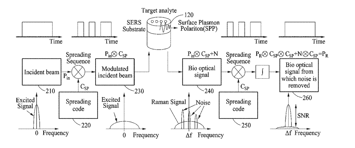
The patent text describes an apparatus and method for improving the performance of a bio optical signal processing device by enhancing the resolution and signal-to-noise ratio of bio optical signals and removing background fluorescence signals. The device includes a modulator that modulates an incident beam and a demodulator that collects the bio optical signal generated in response to the modulated incident beam. The method involves modulating the incident beam with a spreading code and emitting it to a target analyte, where it is scattered and generates a bio optical signal with a correlation to the modulated incident beam. The bio optical signal is then demodulated based on the spreading code to remove noise and obtain a cleaner signal. The technical effect of this patent is to provide a better understanding of the target analyte and reduce background noise in bio optical signal processing.

Problems solved by technology

However, the Raman spectroscopy apparatus may have a disadvantage that a detection sensitivity of the Raman spectroscopy apparatus using a Raman scattering signal is reduced because an intensity of the Raman scattering signal is less than that of an elastic Rayleigh scattering signal having a frequency identical to that of the incident beam.
However, because a degree of polarization of a background fluorescence signal is significant and unstable in real measurement, it is difficult to guarantee a stable function of separating a Raman scattering signal and a noise signal.
However, a performance of a sensing and image technology deteriorates seriously because the related fluorescence scattering signal processing apparatus has difficulty in differentiating the background fluorescence signal and the fluorescence scattering signal generated by performing non-specific binding of an non-target analyte.
However, the washing process is added such that a whole processing process for sensing and imaging becomes complex and there is limitation in representation because a result slightly changes in response to a degree of washing.

Method used


Image

  • Apparatus and method for processing bio optical signal using spread spectrum
  • Apparatus and method for processing bio optical signal using spread spectrum
  • Apparatus and method for processing bio optical signal using spread spectrum

Examples


Embodiment Construction

[0048]Hereinafter, some example embodiments will be described in detail with reference to the accompanying drawings. A method of processing a bio optical signal may be performed by a bio optical signal processing apparatus.

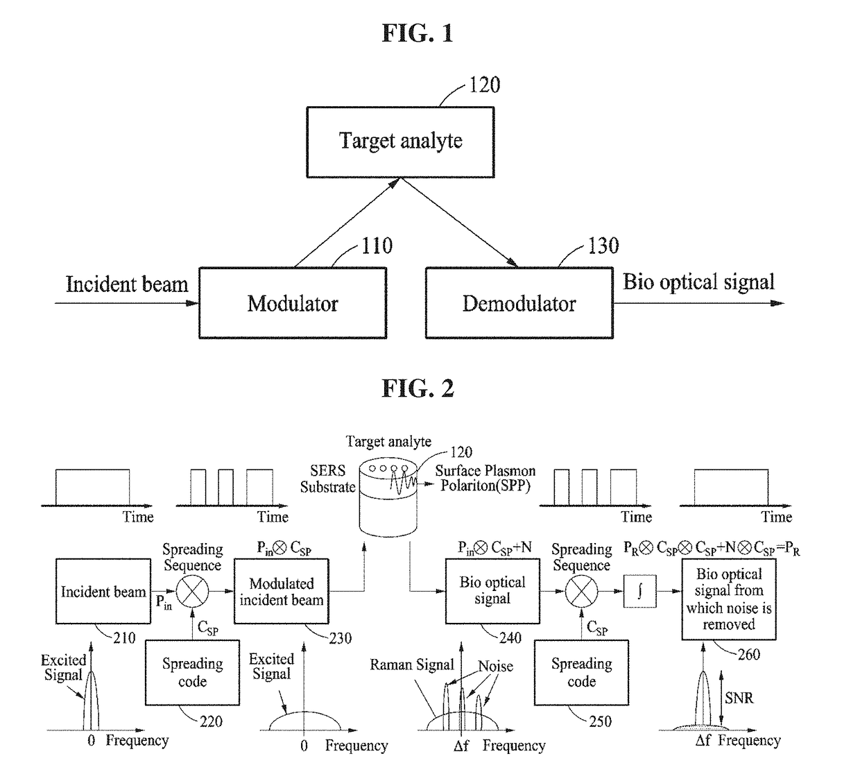
[0049]FIG. 1 is a block diagram illustrating a bio optical signal processing apparatus according to an example embodiment.

[0050]As illustrated in FIG. 1, a bio optical signal processing apparatus 100 includes a modulator 110 and a demodulator 130.

[0051]The modulator 110 may modulate an incident beam incident to the modulator 110 based on a spreading code. The modulator 110 may allow the modulated incident beam to be incident to a target analyte 120. That is, the modulator 110 may spread a spectrum of the incident beam to be emitted to the target analyte 120.

[0052]Here, the modulated incident beam may be scattered from the target analyte 120 to generate a bio optical signal. An attribute of the bio optical signal is different from that of the incident beam, but the...


PUM

PropertyMeasurementUnit
modulation frequencyaaaaaaaaaa
width of wavelength changeaaaaaaaaaa
peak wavelengthaaaaaaaaaa

Abstract

Disclosed is an apparatus and method for processing a bio optical signal based on a spread spectrum scheme including a demodulator configured to collect a bio optical signal generated in response to an incident beam modulated based on a spreading code being scattered from a target analyte, and remove a noise from the bio optical signal by demodulating the bio optical signal based on the spreading code, wherein the bio optical signal has a correlation with the modulated incident beam.

Description

CROSS-REFERENCE TO RELATED APPLICATION(S)[0001]This application claims the priority benefit of Korean Patent Application No. 10-2017-0058132 filed on May 10, 2017, in the Korean Intellectual Property Office, the disclosure of which is incorporated herein by reference for all purposes.BACKGROUND1. Field[0002]One or more example embodiments relate to an apparatus and method for processing a bio optical signal for enhancing performance of sensing and imaging technology by increasing an intensity and a sensitivity of the bio optical signal.2. Description of Related Art[0003]A bio optical signal processing apparatus may perform sensing or imaging on a bio target analyte by analyzing a bio optical signal generated by emitting an incident beam to the bio target analyte. The bio optical signal processing apparatus may include a Raman spectroscopy apparatus and a fluorescence spectroscopy apparatus.[0004]The Raman spectroscopy apparatus may perform sensing or imaging on a cell or a molecule ...

Claims


Application Information

Patent Timeline
Patent Type & Authority Applications(United States)
IPC IPC(8): G01N21/65G01N21/64
CPCG01N21/658G01N21/6428G01N2201/121G01N2201/067G01N2201/06113G01J3/433G01J3/44G01J2001/4242G01N21/274G01N21/47G01N21/65G01N2021/1765G01J2003/4424
Inventor LEE, WON KYOUNGJEONG, KI-HUNPARK, MOONSEONG
Owner ELECTRONICS & TELECOMM RES INST
Learn More