Power supply apparatus and image forming apparatus

a technology of power supply apparatus and image forming apparatus, which is applied in the direction of electric variable regulation, process and machine control, instruments, etc., can solve the problems of increasing the amount of current taken in from a power source, and increasing the cost and the area. , to achieve the effect of increasing the maximum output voltage and simple configuration

Active Publication Date: 2018-11-22
CANON KK
View PDF9 Cites 3 Cited by
  • Summary
  • Abstract
  • Description
  • Claims
  • Application Information

AI Technical Summary

Benefits of technology

[0006]An aspect of the present invention is a power supply apparatus capable of increasing the maximum output voltage thereof with use of a simple configuration.

Problems solved by technology

In this manner, a boost converter circuit that is cost-efficient and area-efficient is achieved without using a transformer, which is expensive and large in size.
However, as easily imagined, an increase of the number of stages of the multistage rectification circuit results in an increase of the cost and the area thereof.
However, the extension of the ON time of the FET means that a larger amount of current is taken in from a power source.
This may limit the supply capacity of the power source, with the result that an influence of a conduction noise becomes larger.
Due to those factors, the sizes of components are increased, and the costs thereof are also increased together with the FET being a drive element.
Some other methods are also conceivable, but under a condition in which the power supply voltage and the number of stages of the multistage rectification circuit cannot be changed, it is difficult to increase the output greatly without an increase in cost of each of the components.

Method used


Image

  • Power supply apparatus and image forming apparatus
  • Power supply apparatus and image forming apparatus
  • Power supply apparatus and image forming apparatus

Examples


first embodiment

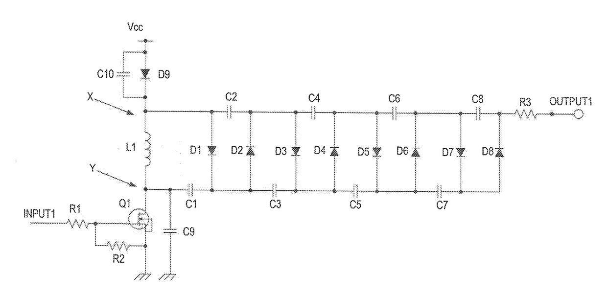
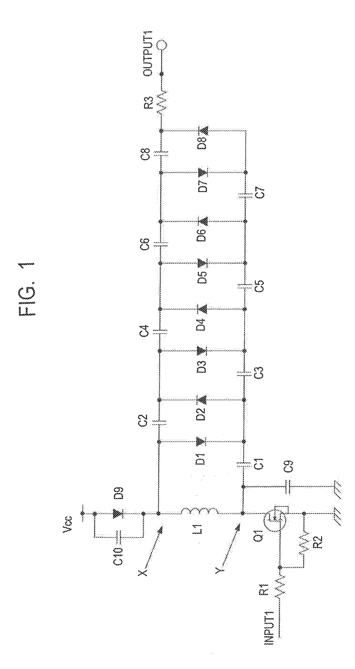
[0020]FIG. 1 is a circuit diagram of a power supply apparatus according to the present invention, and FIG. 8 is a circuit diagram of a power supply apparatus in the related-art example for comparison and reference. First, operation of a circuit of the power supply apparatus in the related-art example is described with reference to FIG. 8. In FIG. 1, the same elements as those of FIG. 8 are denoted by the same reference symbols, and description of parts overlapping with those of FIG. 8 is omitted. The power supply apparatus illustrated in FIG. 8 includes a multistage rectification circuit, and is configured to boost a voltage by repeatedly charging capacitors and adding the voltages. The power supply apparatus includes resistors R1, R2, and R3, a coil L1, a MOSFET (hereinafter referred to as “FET”) Q1, which is a type of field-effect transistor, a capacitor C1 to a capacitor C9, and a diode D1 to a diode D8. Further, “Vcc” represents a DC voltage. One end of the coil L1 serving as an...

third embodiment

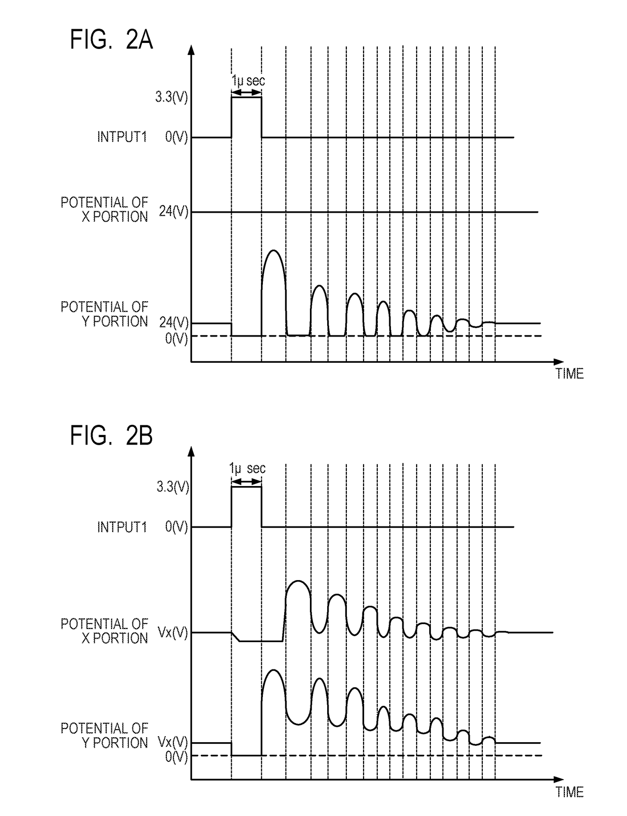
[0044]Consequently, it can be said that the circuit corresponding to FIG. 6B, in which the capacitance elements are connected and the voltage and the frequency at the Y portion are intentionally reduced, has a good balance. However, when the capacitances of the capacitor C9 and the capacitor C10 are set excessively large, the waveforms of the X portion and the Y portion are rounded as a matter of course, and hence the peak potential drops. As a result, the output voltage also drops. In view of the above, at the time of designing the power supply apparatus, it is preferred to seek the optimum capacitance values while the balance of the withstand voltage of the FET Q1, noise, and the output voltage is adjusted. As described above, it is possible to increase the maximum output voltage of the power supply apparatus with use of a simple configuration (only by adding inexpensive components).

[0045]The power supply apparatus described in each of the first to third embodiments is applicable...

fourth embodiment

[0047]A laser beam printer is described as an example of the image forming apparatus according to the present invention. In FIG. 7, a schematic configuration of the laser beam printer as an example of an electrophotographic printer is illustrated. A laser beam printer 300 includes a photosensitive drum 311 serving as an image bearing member on which an electrostatic latent image is to be formed, a charging device 317 (charging unit) configured to uniformly charge the photosensitive drum 311, and a developing device 312 (developing unit) configured to develop the electrostatic latent image formed on the photosensitive drum 311 with toner. A toner image developed on the photosensitive drum 311 is transferred by a transfer device 318 as a transfer unit onto a sheet (not shown) that is a recording material supplied from a cassette 316, as a transfer member. The toner image transferred onto the sheet is fixed by a fixing device 314 and is discharged to a tray 315. The photosensitive drum...


PUM


Abstract

The power supply apparatus includes an inductor; a switching element connected to another end of the inductor, the switching element configured to drive the inductor by being turned on or turned off in accordance with an input pulse signal; a boost converter circuit connected to both ends of the inductor and including a plurality of rectification units, the boost converter circuit configured to amplify a voltage generated in the inductor, each of the plurality of rectification units including a diode and a capacitor; and a voltage boosting element configured to supply a voltage obtained by boosting an input voltage to the inductor.

Description

BACKGROUND OF THE INVENTIONField of the Invention[0001]The present invention relates to a power supply apparatus, for example, a high-voltage power supply configured to generate a high voltage, and an image forming apparatus including the power supply apparatus.Description of the Related Art[0002]Hitherto, there are various products that handle a high voltage. Examples thereof include air cleaners, air conditioners, ionizers, cathode ray tube televisions, laser printers, and particle accelerators. In many cases, a high voltage is generated by boosting a low voltage, and there are several types of circuits for generating the high voltage. Among the several types of circuits, a circuit called Cockcroft-Walton circuit is often employed. In the Cockcroft-Walton circuit, capacitors and diodes are connected to one another in a ladder-like manner to repeatedly perform charge / discharge and addition of voltages, to thereby boost the voltage. The Cockcroft-Walton circuit can be achieved with ...

Claims


Application Information

Patent Timeline
Patent Type & Authority Applications(United States)
IPC IPC(8): G05F1/10H02M3/07H02M3/158H02M7/10H02M1/42
CPCG03G15/80H02M3/07H02M3/1582H02M7/103H02M1/4225H02M3/158H02M1/0095H02M3/156
Inventor HIRABAYASHI, JUN
Owner CANON KK
Why Eureka
Try Eureka