Hybrid separators and the manufacture thereof

Active Publication Date: 2018-11-22
CORNELL UNIVERSITY
View PDF1 Cites 10 Cited by
  • Summary
  • Abstract
  • Description
  • Claims
  • Application Information

AI Technical Summary

Benefits of technology

The patent describes an improved separator and material that can be used in batteries. The new separators have better strength and can withstand more punishment during charging and discharging, while also being thinner than typical commercial separators. This means that less material is needed in a battery, which can make it more efficient.

Problems solved by technology

As year-over-year lithium ion battery capacity improvements have failed to keep up with demand, many battery companies have become aggressive in their attempts to improve capacity, sometimes at the expense of safety.
For example, according to the New York Times, Samsung's recent difficulties with their consumer electronic lithium ion batteries have resulted from design flaws because of their “aggressive design decisions, which made problems more likely.” In particular, “[i]n the Note 7, Samsung opted for an exceptionally thin separator in its battery” in order to increase active material loading in the battery and, thereby, increase battery capacity.
Because of the extremely thin nature of the separator, a much greater likelihood of failure was likely “if it breaks down, varies in thickness or is damaged by outside pressure.”

Method used


Image

  • Hybrid separators and the manufacture thereof
  • Hybrid separators and the manufacture thereof
  • Hybrid separators and the manufacture thereof

Examples


example 1

ray Polymer Film Membrane

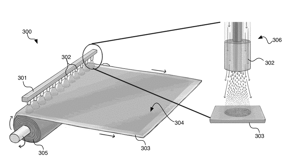
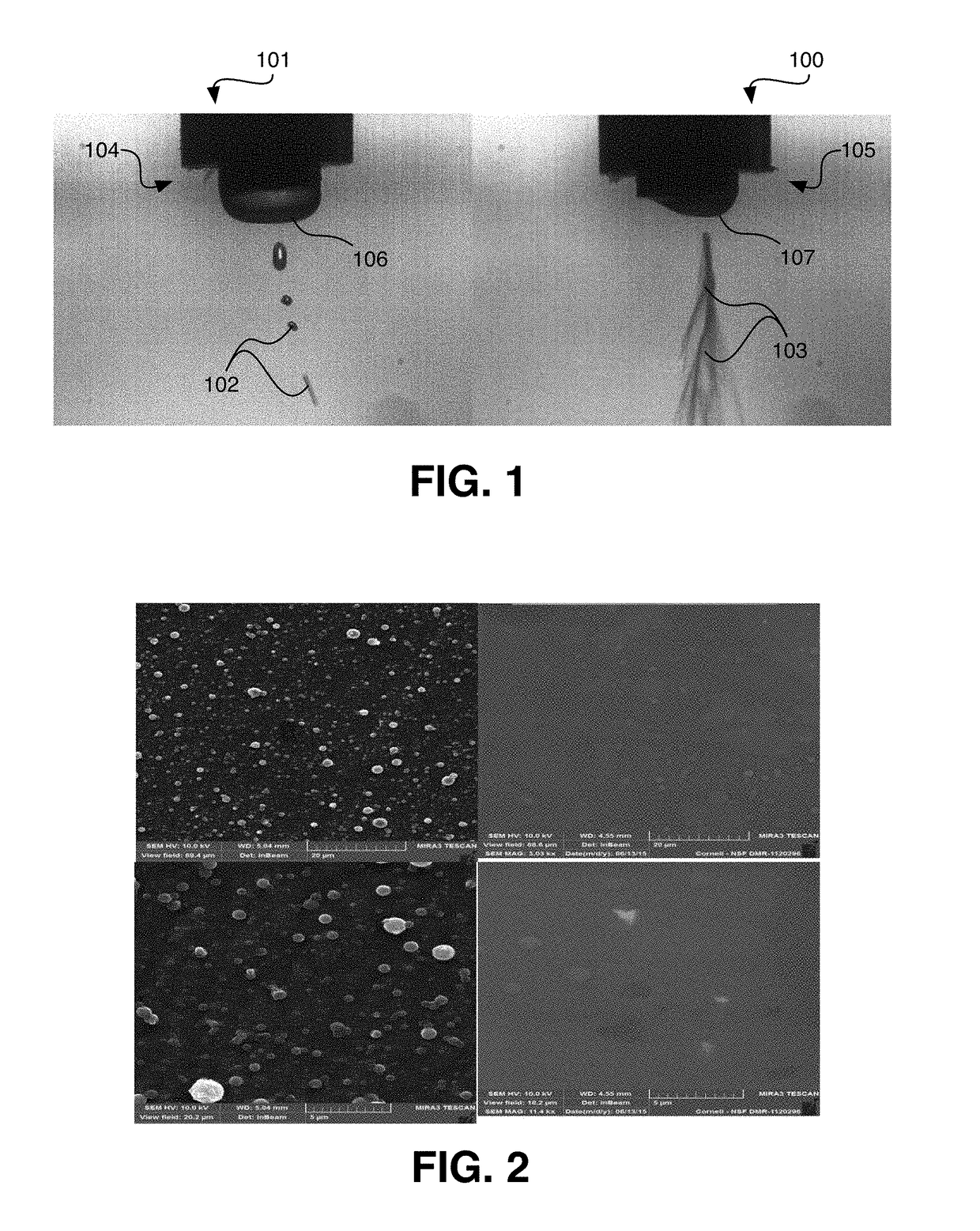
[0148]A fluid stock comprising 1-5 wt. % polyvinylalcohol (PVA) in water is prepared. The solution is provided to a non-gas-controlled electrospray nozzle, to which a direct voltage of about 10 kV to about 15 kV is maintained. A grounded collector is positioned opposite the electrospray nozzle, at a distance of about 20 cm to about 25 cm. High speed imaging of the electrospray process is illustrated in FIG. 1 (left panel), and a PVA deposition is collected on the collector, as illustrated in FIG. 2 (left panels). As is illustrated in FIG. 2, the deposition is irregular, with large PVA beads being evident.

[0149]A 1-5 wt. % PVA solution is also electrosprayed by injecting the solution into a gas (air) stream (Qair of about 11 SCFH) using a coaxially configured nozzle as described herein. A direct voltage of about 10 kV to about 15 kV is maintained at the nozzle. A grounded collector is positioned opposite the electrospray nozzle, at a distance of about 20 cm t...

example 2

in Polymer Fiber Mat Membrane

[0150]A fluid stock is prepared similar to as described in Example 1, with a concentration of >5% polyvinylalcohol (PVA) in water. The solution is provided to a gas-controlled electrospin nozzle, to which a direct voltage of about 10 kV to about 15 kV is maintained. A grounded collector is positioned opposite the electrospin nozzle, at a distance of about 20 cm to about 25 cm. Fibers are electrospun with gas under conditions similar to those identified in Example 1.

example 3

eramic Hybrid Membrane

[0151]Using a process similar to that described in Example 2, a fluid stock is prepared using polyacrylonitirle (PAN) in DMF (8-15 wt. %) and adding a ceramic precursor (a silazane). The fluid stock is processed using a similar gas-assisted process as described in Example 2 and collected. The fibers are cured at a rate suitable for obtaining a continuous ceramic matrix (co-continuous with polymer), with a ceramic coat. A fibrous mat is collected and prepared into a membrane, such as illustrated in FIG. 10.

[0152]A strip of the membrane is prepared. One end of the membrane strip placed into an electrolyte bath. A strip of conventional polyolefinic separator (CELGARD® 2400) is similarly treated. After allowing the electrolyte to absorb into the membranes (wick), the uptake of electrolyte is compared. FIG. 10 illustrates the dramatically improved wettability of an exemplary polymer-ceramic hybrid membrane material provided herein relative to a polypropylene (PP) se...


PUM

PropertyMeasurementUnit
Lengthaaaaaaaaaa
Lengthaaaaaaaaaa
Fractionaaaaaaaaaa

Abstract

Provided herein are a variety of porous separator materials, particularly those prepared by gas-assisted electrospray and electrospinning processes.

Description

CROSS REFERENCE TO RELATED APPLICATIONS[0001]This application claims priority to U.S. Provisional Application No. 62 / 506,973, filed on May 16, 2017, the disclosure of which is hereby incorporated by reference.BACKGROUND OF THE INVENTION[0002]Batteries comprise one or more electrochemical cell, such cells generally comprising a cathode, an anode and an electrolyte. Lithium ion batteries are high energy density batteries that are fairly commonly used in consumer electronics and electric vehicles. In lithium ion batteries, lithium ions generally move from the negative electrode to the positive electrode during discharge and vice versa when charging. In the as-fabricated and discharged state, lithium ion batteries often comprise a lithium compound (such as a lithium metal oxide) at the cathode (positive electrode) and another material, generally carbon, at the anode (negative electrode).[0003]The commercial importance of battery safety has recently become critically clear in the wake of...

Claims


Application Information

Patent Timeline
IPC IPC(8): H01M2/16H01M2/14H01M10/0525C25D1/08H01M50/403H01M50/414H01M50/42H01M50/434H01M50/451H01M50/491
CPCH01M2/166H01M2/145H01M2/1653H01M2/1646H01M10/0525C25D1/08H01M10/4235Y02E60/10H01M50/403H01M50/44H01M50/451H01M50/491H01M50/414H01M50/434H01M50/42H01M50/446
Inventor JOO, YONG LAKCARLIN, JOSEPH M.SMITH, SOSHANA
Owner CORNELL UNIVERSITY
Why Eureka
Try Eureka