
Methods and Apparatus for Predicting Performance of a Measurement Method, Measurement Method and Apparatus

a measurement method and measurement method technology, applied in the direction of optical radiation measurement, photomechanical equipment, instruments, etc., can solve the problems of difficult measurement of wavefronts in the spectral region of extreme ultraviolet (euv) and soft x-ray (sxr) spectral regions, and the inability to directly measure the smallest features of modern lithographic processes. achieve the effect of further separation of spectral components and increase of spatial resolution

Active Publication Date: 2018-12-06
ASML NETHERLANDS BV
View PDF3 Cites 15 Cited by
  • Summary
  • Abstract
  • Description
  • Claims
  • Application Information

AI Technical Summary

Benefits of technology

The invention allows for the creation of an array of locations with dispersive elements that have different directions of dispersion, which prevents interference between the spectral components from different locations. Additionally, the array can be divided into subsets with different directions of dispersion to achieve higher spatial resolution and further separate the spectral components of the different locations.

Problems solved by technology

This limits the smallest features that can be measured, so that the technique can no longer measure directly the smallest features made in modern lithographic processes.
Measurement of wavefronts in the extreme ultraviolet (EUV) and soft x-ray (SXR) spectral region is challenging because of high absorption by most materials and the difficulty to fabricate focusing optics.
While fast spectrum measurements exist, a fast 2-D wavefront measurement can only be done without spectral resolution, i.e. integrated over the full spectrum of the source.
To measure the wavefront with spectral resolution and 2-D would then require a scanning process, which would be slow and cumbersome.
Unfortunately, these techniques reduce the spatial resolution of the sensor in proportion to the number of colors, and color filters are not readily available for EUV / SXR wavelengths.

Method used


Image

  • Methods and Apparatus for Predicting Performance of a Measurement Method, Measurement Method and Apparatus
  • Methods and Apparatus for Predicting Performance of a Measurement Method, Measurement Method and Apparatus
  • Methods and Apparatus for Predicting Performance of a Measurement Method, Measurement Method and Apparatus

Examples


application examples

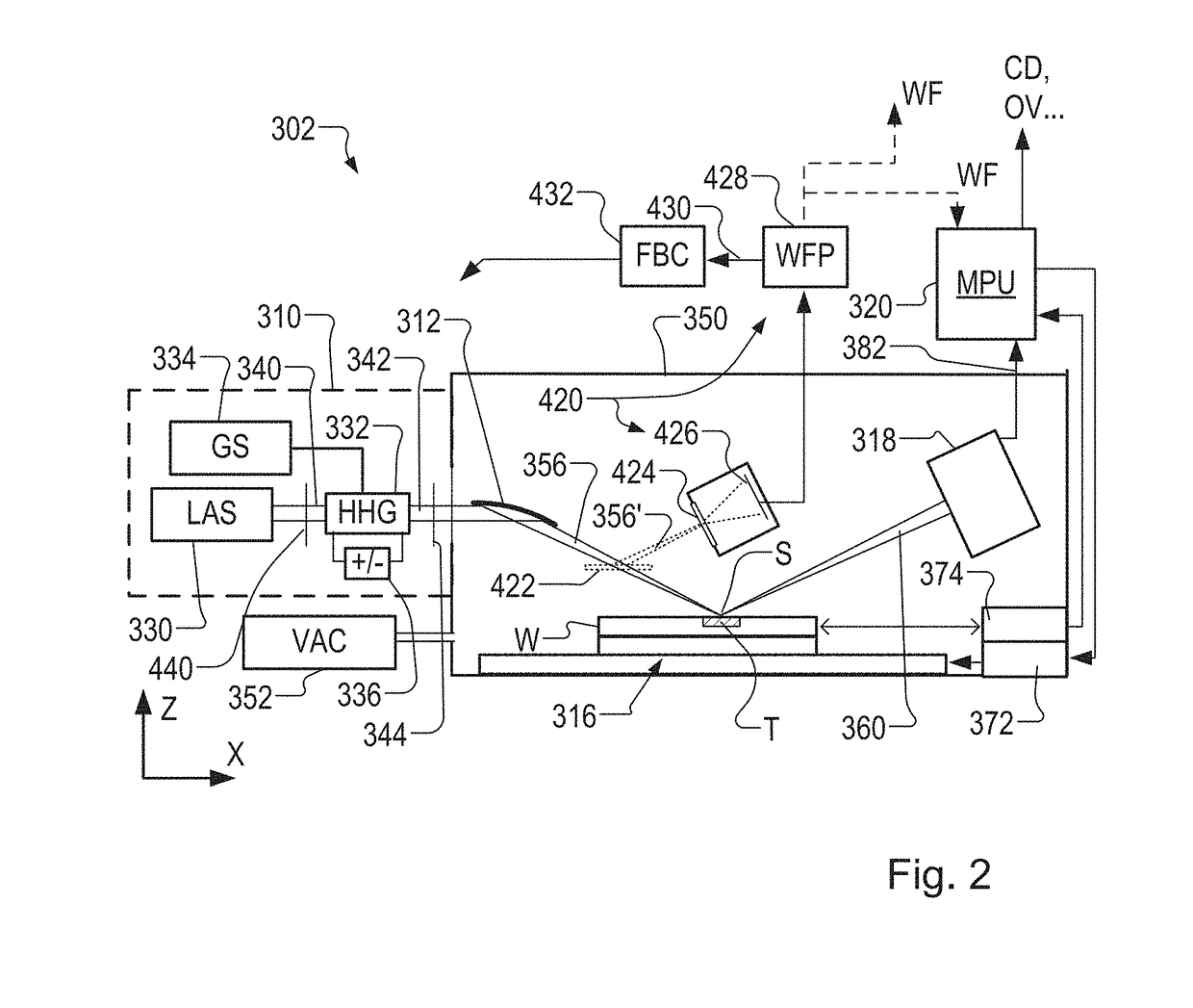
[0153]In any of the above examples, the spectrally resolved and spatially resolved information obtained from the modified wavefront sensor 420 can be used to monitor and / or adjust numerous parameters of the operating radiation source arrangement

[0154]Examples of parameters and conditions that can be monitored in real time (and adjusted automatically or manually) include:[0155]1) Direction of the pump radiation[0156]2) Positioning of the pump radiation focus[0157]3) The wave front of the pump radiation (for example by modifying or reprogramming a Spatial Light Modulator 440)[0158]4) Gas flow settings, nozzle shape and other gas jet parameters[0159]5) Gas jet nozzle deterioration[0160]6) Gas composition and purity

[0161]Since the wavefront sensor in this example is positioned downstream of the focusing arrangement in the illumination system 312, parameters and conditions within the illumination system can be monitored, either separately, or as parameters of the radiation source and ill...


PUM

PropertyMeasurementUnit
wavelengthsaaaaaaaaaa

Abstract

A metrology apparatus (302) includes a higher harmonic generation (HHG) radiation source for generating (310) EUV radiation. Operation of the HHG source is monitored using a wavefront sensor (420) which comprises an aperture array (424, 702) and an image sensor (426). A grating (706) disperses the radiation passing through each aperture so that the image detector captures positions and intensities of higher diffraction orders for different spectral components and different locations across the beam. In this way, the wavefront sensor can be arranged to measure a wavefront tilt for multiple harmonics at each location in said array. In one embodiment, the apertures are divided into two subsets (A) and (B), the gratings (706) of each subset having a different direction of dispersion. The spectrally resolved wavefront information (430) is used in feedback control (432) to stabilize operation of the HGG source, and / or to improve accuracy of metrology results.

Description

FIELD[0001]The present disclosure relates to methods and apparatus for inspection (e.g., metrology) usable, for example, in the manufacture of devices by lithographic techniques and to methods of manufacturing devices using lithographic techniques.BACKGROUND[0002]A lithographic apparatus is a machine that applies a desired pattern onto a substrate, usually onto a target portion of the substrate. A lithographic apparatus can be used, for example, in the manufacture of integrated circuits (ICs). In that instance, a patterning device, which is alternatively referred to as a mask or a reticle, may be used to generate a circuit pattern to be formed on an individual layer of the IC. This pattern can be transferred onto a target portion (e.g., including part of, one, or several dies) on a substrate (e.g., a silicon wafer). Transfer of the pattern is typically via imaging onto a layer of radiation-sensitive material (resist) provided on the substrate. In general, a single substrate will con...

Claims


Application Information

Patent Timeline
Patent Type & Authority Applications(United States)
IPC IPC(8): G01N21/88G01N21/95G01J1/42
CPCG01N21/8806G01N21/9501G01J1/42G01J2001/4247G01J9/00G03F7/70133G03F7/70141G03F7/70191G03F7/706G01J1/4257G01J2009/002
Inventor WITTE, STEFAN MICHIELJANSEN, GIJSBERT SIMON MATTHIJSFREISEM, LARS CHRISTIANEIKEMA, KJELD SIJBRAND EDUARDMATHIJSSEN, SIMON GIJSBERT JOSEPHUS
Owner ASML NETHERLANDS BV
Learn More