
Fault detection device for internal combustion engine

a technology of internal combustion engine and fault detection device, which is applied in the direction of combustion air/fuel air treatment, electric control, instruments, etc., can solve the problem of leakage fault of recirculation pipe that cannot be detected, and achieve the effect of high precision, high precision, and relatively high inner pressure of crankcas

Inactive Publication Date: 2018-12-27
DENSO CORP
View PDF0 Cites 17 Cited by
  • Summary
  • Abstract
  • Description
  • Claims
  • Application Information

AI Technical Summary

Benefits of technology

This patent is about a device that can detect leaks in the recarburation pipes of internal combustion engines, which can cause problems in the engine's performance. The device is capable of accurately measuring the pressure in the engine's crankcase, and can quickly detect any leaks in the recarburation pipes, allowing for quick repair. Overall, this device can help prevent damage to the engine and improve its performance.

Problems solved by technology

According to the above configuration, even in the supercharge region where the pressure in the crank case and the pressure in the surge tank become positive pressures, the evaporated fuel can be returned to the combustion chamber again and can cause the recombustion.
However, in the engine with the supercharger that has the configuration of the recirculation pipe, the leakage fault of the recirculation pipe cannot be detected according to a leakage determination processing disclosed in Patent Literature 1.

Method used


Image

  • Fault detection device for internal combustion engine
  • Fault detection device for internal combustion engine
  • Fault detection device for internal combustion engine

Examples


first embodiment

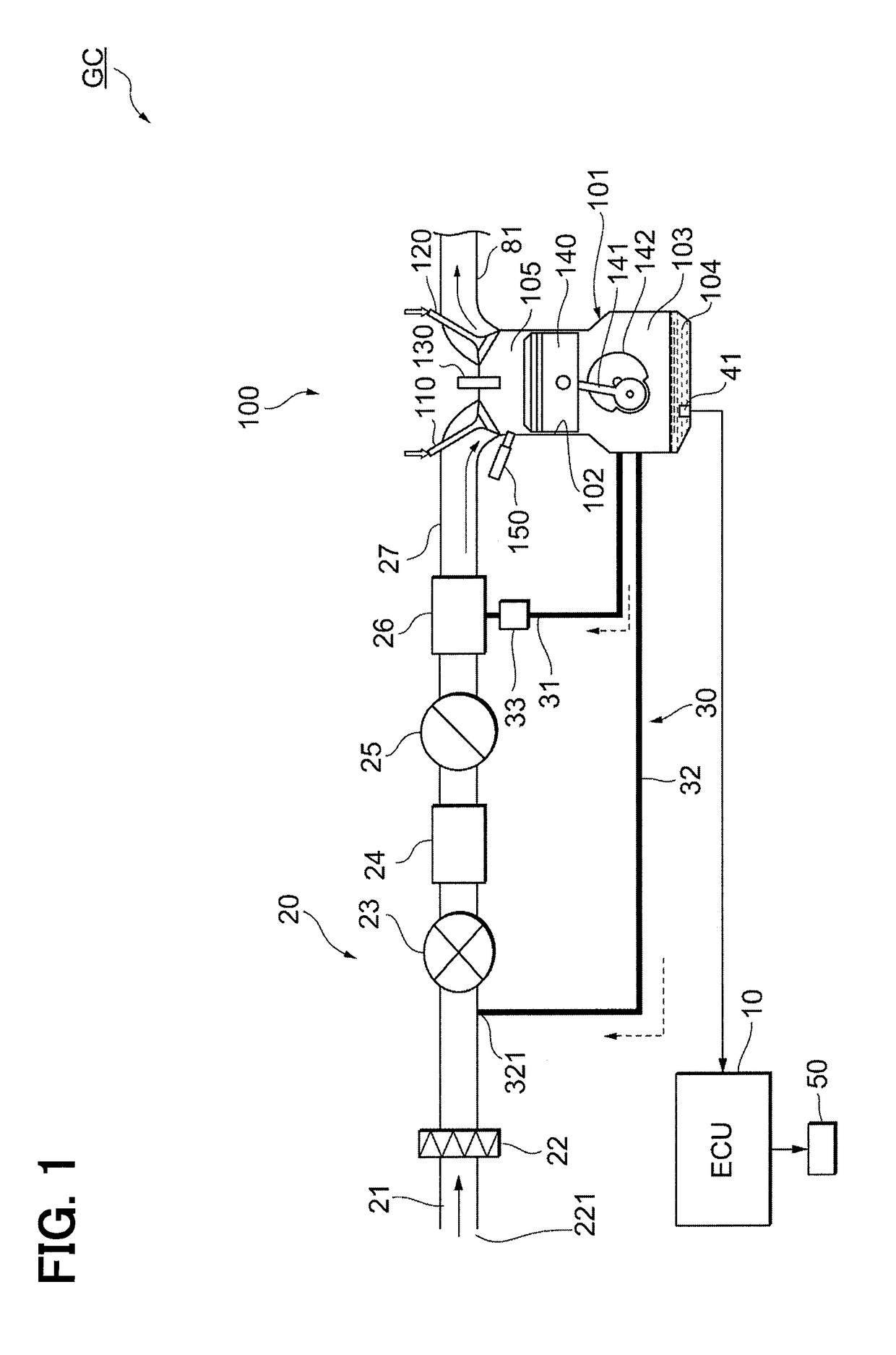
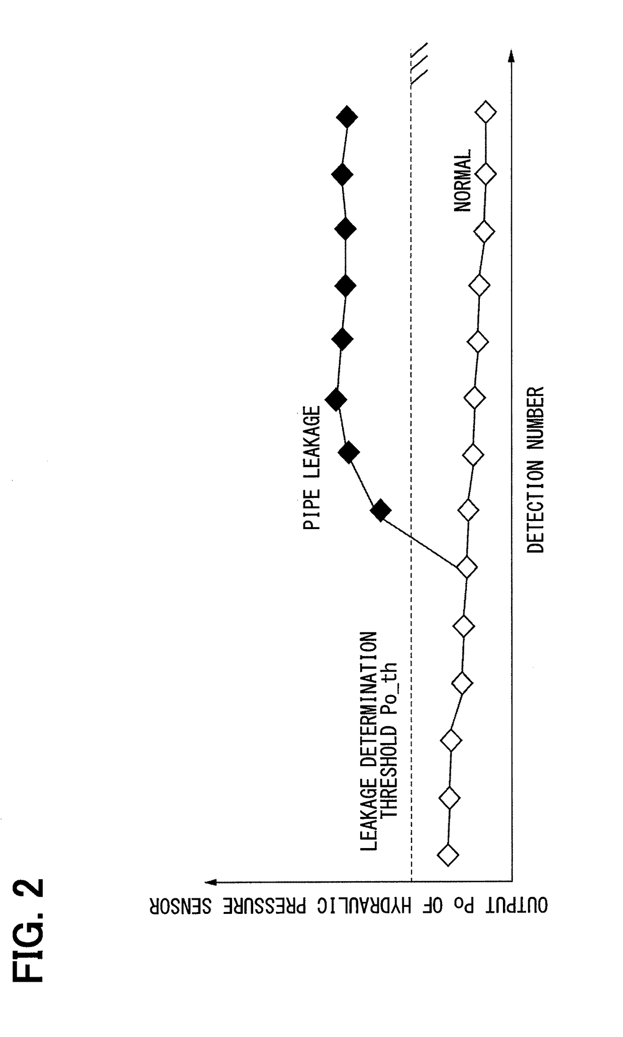
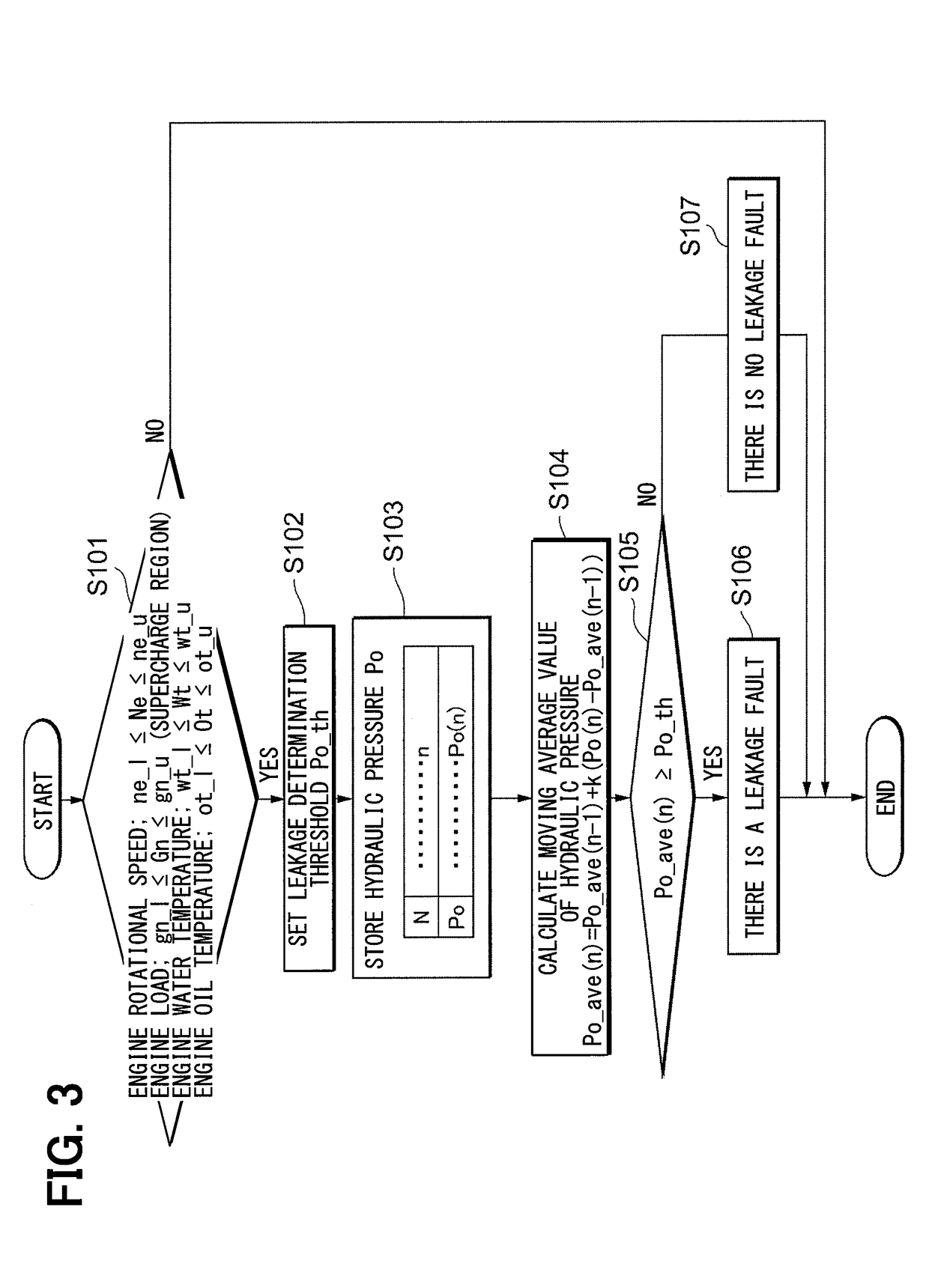
[0019]A first embodiment will be described referring to FIGS. 1 to 3. According to the first embodiment, a constitution of a vehicle GC to which a fault detection device of an internal combustion engine is applied will be described referring to FIG. 1. As shown in FIG. 1, the vehicle GC includes an electronic control unit (ECU) 10, an engine 100, an intake system 20 and a PCV system 30.

[0020]The engine 100 is an internal combustion engine that uses a gasoline as a fuel. The engine 100 is located in an engine room of the vehicle GC. The engine 100 includes multiple cylinders. Since each of the cylinders has the same configuration, a single cylinder is shown in FIG. 1.

[0021]A cylinder 102 that is a cylindrical shape and a crank case 103 are located in a cylinder block 101 of each of the cylinders of the engine 100. The crank case 103 is located at a position lower relative to the cylinder 102. The cylinder 102 receives a piston 140 that is slidable relative to the cylinder 102 in an u...

second embodiment

[0074]A second embodiment will be described referring to FIGS. 4 to 6. According to the second embodiment, matters that the crank-case inner pressure is directly measured, the determination of the leakage fault of the second PCV pipe 32 is executed by using the crank-case inner pressure that is measured are different from the first embodiment.

[0075]As shown in FIG. 4, the fault detection device of the internal combustion engine according to the second embodiment includes a pressure sensor 42. The pressure sensor 42 is a sensor that generates and sends a signal corresponding to the crank-case inner pressure. The pressure sensor 42, for example, as shown in FIG. 4, is located in the vicinity of the connection part 321 of the second PCV pipe 32 between the second PCV pipe 32 and the intake pipe 21.

[0076]An installation position of the pressure sensor 42 may be located in the vicinity of a connection part 322 of the second PCV pipe 32 between the second PCV pipe 32 and the crank case 10...


PUM


Abstract

A fault detection unit of an internal combustion engine includes a recirculation pipe connected with an upstream-side part of an intake pipe of the internal combustion engine upstream of a supercharger, the recirculation pipe to supply an evaporated fuel that is unburned and is generated in the internal combustion engine to the intake pipe, and a fault detection unit to detect a leakage occurrence of the recirculation pipe based on a crank-case inner pressure of the internal combustion engine when the internal combustion engine is operating in a specified operation condition that the crank-case inner pressure is a positive pressure.

Description

CROSS REFERENCE TO RELATED APPLICATION[0001]This application is based on Japanese Patent Application No. 2015-248327 filed on Dec. 21, 2015, the disclosure of which is incorporated herein by reference.TECHNICAL FIELD[0002]The present disclosure relates to a fault detection device of an internal combustion engine which detects a leakage occurrence of a recirculation pipe supplying an evaporated fuel to a position of an intake pipe of the internal combustion engine upstream of a supercharger.BACKGROUND ART[0003]It is known that a positive crankcase ventilation device (PCV device) that is a device forcibly exchange gas in a crank case in an internal combustion engine is provided for an object to suppress an environment deterioration caused by a fuel component that is diluted (mixed) in an engine oil and volatilizes to the atmosphere. As the PCV device, for example, according to Patent Literature 1, a device that an evaporated fuel (blow-by gas) in a crank case can be returned to a comb...

Claims


Application Information

Patent Timeline
Patent Type & Authority Applications(United States)
IPC IPC(8): F01M13/00F02D23/00F02D41/00F02M35/10G01M15/09G01M15/04
CPCF01M13/00F02D23/00F02D41/003F02M35/10006F02M35/10157F02M35/10222G01M15/09G01M15/048F02D2200/021F01M2013/0083F01M2250/60F02D41/0007F02D41/0032F02D41/22F02D2200/024G01M3/025Y02T10/12Y02T10/40
Inventor NAKANO, KOSUKEKUROSAWA, MASANORI
Owner DENSO CORP
Learn More